


Reelmaster 5010- HPage 5 - 44Electrical System
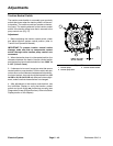
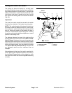
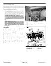
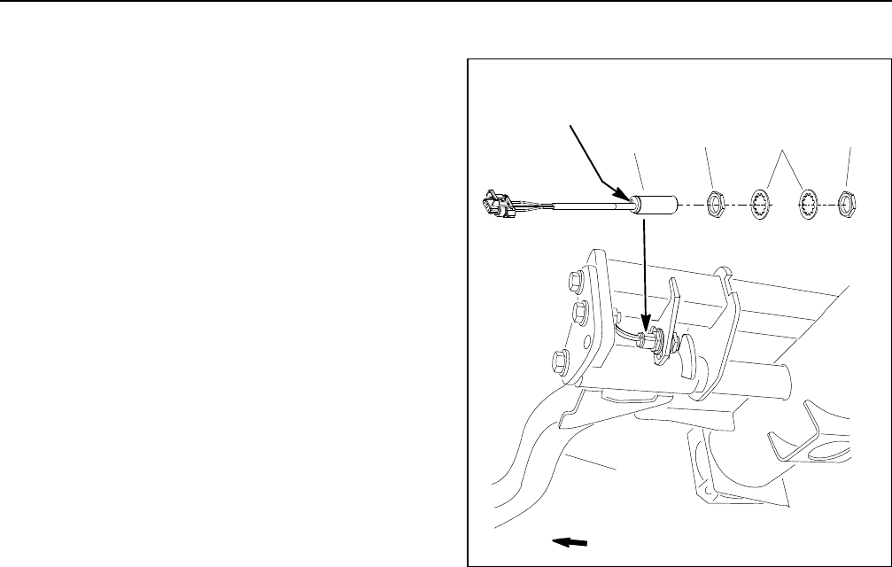
Cutting Unit Down Limit Switch
The cutting unit down limit switch is a normally open
proximity switch that closes when the front, outside cut-
ting unitsare in theturn- around position. Thedown limit
switch is attached to a frame bracket inside the front,
right lift arm pivot tube. A bracket on the front, right lift
arm acts as the se nsing plate for the down limit switch
(Fig. 29).
Adjustment
The down limit switch should be secured to the switch
bracket at the midpoint of the bracket mounting slots.
NOTE: The vertical location of the down limit switch on
the switch bracket will determine the turn- around posi-
tion of the front, outside cutting units (cutting units #4
and #5). Raising the switch on the bracket will allow a
lowerturn- aroundposition ofthecutting units.Lowering
the switchon the bracketwill allow ahigher turn- around
position of the cutting units.
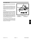
The distance between the down limit switch and the
sensingplateonliftarm shouldbefrom0.094”to0.100”
(2.4 to 2.5 mm). If distance is incorrect, loosen jam nuts
that securedown limitswitch tomachine frame. Position
switch with jam nuts to allow correct clearance between
switch and sensing plate. Jam nuts should be t orqued
from 162to 198in- lb (18.4to 22.4N- m) .After jamnuts
are tightened, make sure that clearance has not
changed.
After adjustment to the down limit switch, use the Info-
Center Display (see Diagnostics Screen (PTO item) in
the InfoCenter Display section of t his chapter) to verify
that down limit switch and circuit wiring are functioning
correctly.
1. Down limit switch
2. Lock washer
3. Jam nut
4. Lift arm
Figure 29
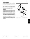
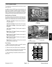
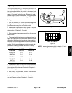
LED Location
FRONT
2
3
1
3
4
Switch