


Reelmaster 5010- H Page 3 - 11 Kubota Diesel Engine
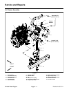
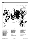
Removal (Fig. 8)
1. Park machine on a level surface, lower cutting
decks, stop engine, apply parking brake and remove
key from the ignition switch.
2. Unlatch r ear screen, lift screen from hinges and re-
move screen from machine.
3. Remove 12 volt battery from rear of machine toease
oil cooler removal (see 12 VDC Battery Service in the
Service and Repairs section of C hapter 5 - Electrical
System).
4. Rotate clamps that secure oil cooler to radiator
frame. Carefully lift and remove oil cooler from radiator
frame. Position and support oil cooler away from the ra-
diator.
5. Raise and support the hood.
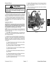
CAUTION
Do not open radiator cap or drain coolant if the
radiator or engine is hot. Pressurized, hot cool-
ant can escape and cause burns.
Ethylene-glycol antifreeze is poisonous. Dis-
pose of coolant properly, or store itin aproperly
labeled container away from children and pets.
6. Drain radiator into a suitable container either by us-
ing the draincock (item 16) on the left side of the radiator
or by disconnecting the lower radiator hose from the ra-
diator. Make sure that drain container is large enough to
hold cooling system contents (see Specifications in this
Chapter).
IMPORTANT: Follow all local codes and regula-
tions when recycling or disposing engine coolant.
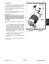
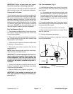
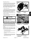
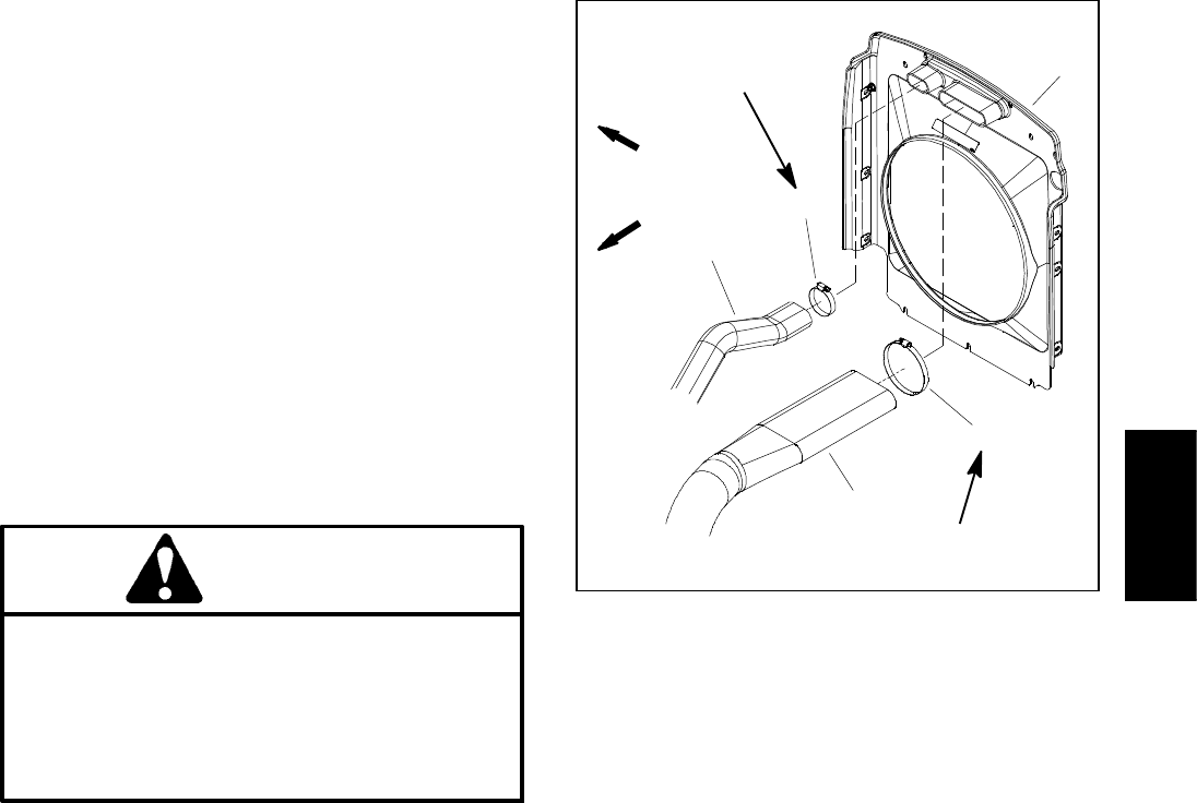
7. Disconnect air cleaner and motor/generator intake
hoses from fan shroud (Fig. 9).
8. Disconnect radiator hoses (upper and lower) from
the radiator .
9. At rear of radiator frame, carefully cut the upright
foam seals (item 4) at the junction of the radiator frame
andthemachine frame. This willallowthe radiatorframe
to be removed from the machine without removing the
foam seal from the radiator and machine frames.
10.Remove six (6) washer head screws (item 31) that
secure the radiator frame (item 19) to the frame.
11.Carefully raise radiator assembly (radiator, fan
shroud, coolant reservoir and radiator frame) from the
machine.
Figure 9
1. Fan shroud
2. Air cleaner intake hose
3. Hose clamp
4. G e nerator i ntake hose
5. Hose clamp
2
3
1
4
5
FRONT
RIGHT
30 to 40 in-lb
(3.4 to 4.5 N-m)
30 to 40 in-lb
(3.4 to 4.5 N-m)
12.Plug radiator and hose openings to prevent contami-
nation.
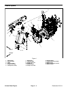
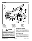
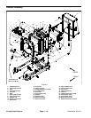
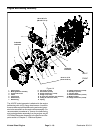
13.Disassemble radiator assembly as needed using
Figure 8 as a guide.
Installation (Fig. 8)
1. Inspect all foam seals placed between radiator, fan
shroud and radiator frame. Replace damaged foam
seals.
2. Remove plugs placed in radiator and hose openings
during the removal procedure.
3. Install a ll removed components to radiator frame us-
ing Figure 8 as a guide.
4. Carefully lower radiator assembly with radiator, fan
shroud, coolant reservoir and radiator frame to the ma-
chine frame.
5. Secure the radiator frame (item 19) to the frame with
six (6) washer head screws (item 31).
6. Make sure that at least 0.250” (6.4 mm) clearance
exists at all points between fan shroud opening and fan.
7. Connect upper and lower radiator hoses to radiator
and secure with hose clamps. Torque hose clamps from
30 to 40 in- lb (3.4 to 4.5 N-m).
Kubota Diesel
Engine