


Reelmaster 5010- H Page 5 - 43 Electrical System
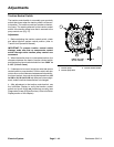
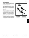
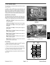
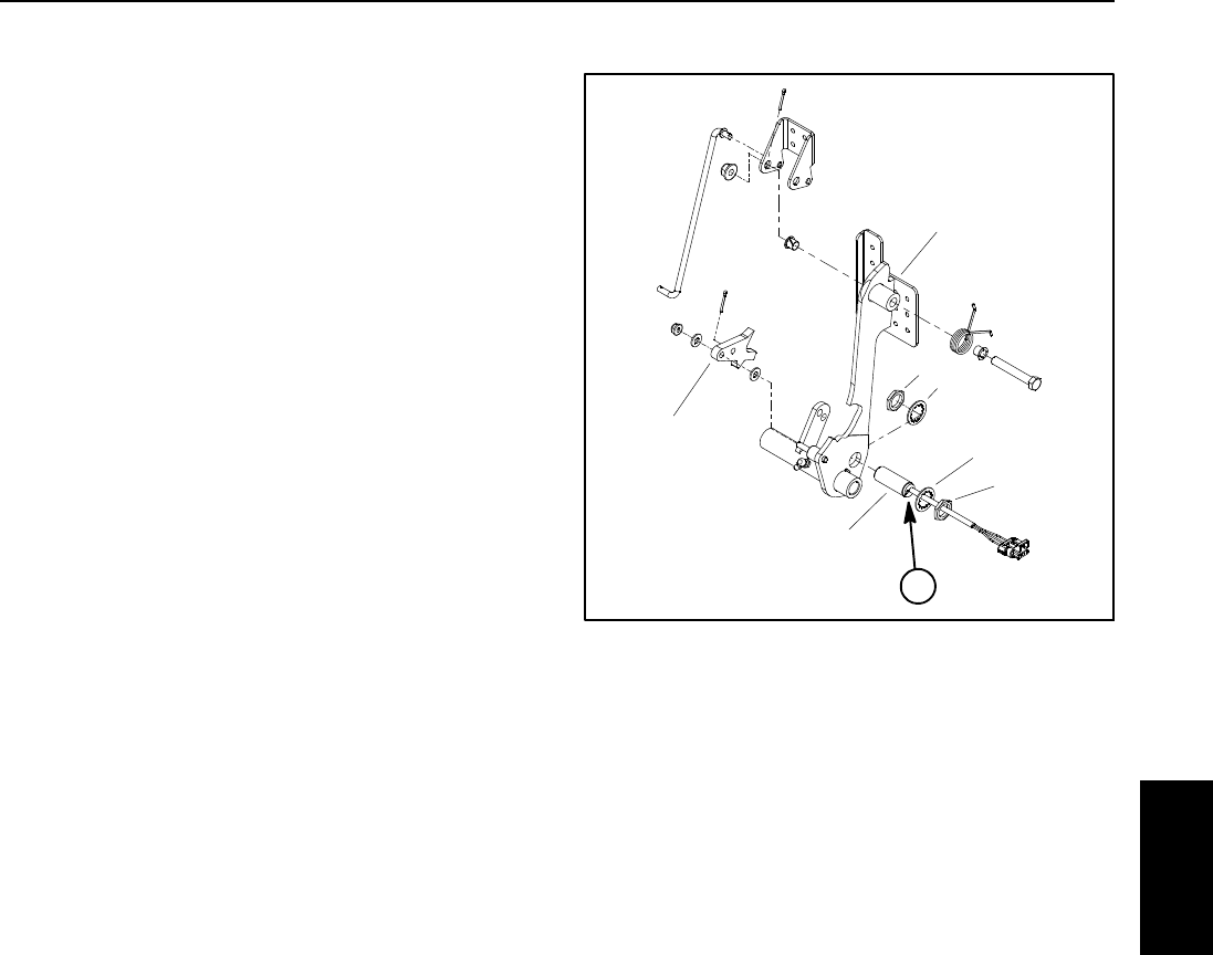
Parking Brake Switch
The parking brake switch is a normally open proximity
switch. The parking brake switch is attached to the bot-
tom of the brake pedal (Fig. 28).
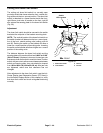
Whentheparking brakeisnot applied,theparkingbrake
detent is positioned near the target end of the parking
brake switch so the switch is closed. The parking brake
detent is moved away from the switch when the parking
brake is applied causing the switch to open.
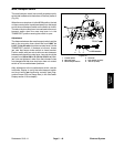
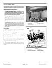
Adjustment
The distance between th e parking brake switch and the
tab on the parking brake detent should be from 0.094”
to 0.100” (2.4 to 2.5 mm) when the parking brake is not
applied. If distance is incorrect, loosen jam nuts that se-
cure brake switch to brake pedal. Position switch with
jam nuts to allow correct clearance between switch and
brake detent tab. Jam nuts should be torqued from 162
to198in-lb(18.4to22.4N-m).After jamnuts aretight-
ened, make sure that clearance has not changed.
After adjustment to the parking brake switch, use the In-
foCenter Display to verify that brake switch and circuit
wiring arefunctioning correctly(see Diagnostics Screen
(Engine Run item) in the InfoCenter Display section of
this chapter).
1. Parking brake switch
2. Lock washer (2 used)
3. Jam nut (2 used)
4. Parking brake detent
5. Brake pedal
6. Switch LED location
Figure 28
2
3
4
5
1
2
3
6
Electrical
System