


Reelmaster 5010- HPage 3 - 16Kubota Diesel E ngine
9. Disconnect h ydraulic pump drive shaft from 48 VDC
motor/generator (see Hydraulic Pump Drive Shaft in the
Service and Repairs section of Chapter 4 - Hydraulic
System). Position and support drive shaft away from
motor/generator and engine.
IMPORTANT: To prevent damage to electrical wire
harness, numerous cable ties are used to secure
harness to machine components. Take note of all
cable ties that are removed from machine during
engine removal so they can be properly replaced
during engine installation.
10.Note location of cable ties used to secure wire har-
ness tothe machineforassembly purposes. Disconnect
wires and/or electrical connections from the following
engine electrical components:
A. The wire harness connectors from the alternator,
temperature sender, oil pressure switch, starter mo-
tor solenoid and fuel actuator.
B. The wire harness ring terminals from the alterna-
tor and glow plug bus.
C. The positive battery cable and fusible link har-
ness from the engine starter motor.
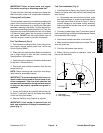
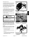
D. The negative battery cable and wire harness
ground at the engine block under the fuel actuator
(Fig. 12).
E. The wire harness connector from the 48 VDC
motor/generator assembly.
CAUTION
Make sure that hoist or lift used to remove en-
gine assembly can properly support engine and
attached components. Engine assembly weighs
approximately 280 pounds (127 kg).
11.Connect suitable lift or hoist to the lift brackets on
each end of the engine cylinder head.
12.Remove flange nuts, rebound washers, spacers and
cap screws that s ecure the engine mount brackets to
the engine mounts.
CAUTION
One person should operate hoist or lift while a
second person guides the engine out of the ma-
chine.
IMPORTANT: Make sure to not damage the engine,
fuel hoses, hydraulic lines, electrical harness, ra-
diator or other parts while removing the engine.
13.Carefully raise engine from machine moving it to-
ward thefront of themachineand awayfrom radiatoras-
sembly.
14.If necessary, remove engine mount brackets from
engine.
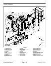
15.If necessary, remove engine mounts from machine
frame (Fig. 13). Note that front engine mount on left side
of machine has the negative battery cable ground con-
nection secured with one ofthe mount bolts. If removed,
make sure to locate lock washer that should be installed
between the c able connection and the frame.
16.If necessary, remove 48 VDC motor/generator from
engine (see 48 VDC Motor/Generator Assembly in the
Service and Repairs section of C hapter 5 - Electrical
System).
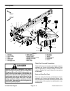
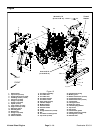
Engine Installation (Fig. 10)
1. Locate machine on a level surface with cutting units
lowered and key removed from the ignition switch.
Chock wheels to keep the m achine from moving.
2. Make sure that all parts removed from the engine
during maintenance or rebuilding are installed to the en-
gine.
3. If enginemount brackets were removed from the en-
gine, secure brackets to engine with lock w ashers and
cap screws. Torque cap screws from 34 to 42 ft- lb (47
to 56 N- m).
4. If removed, install 48 VDC motor/generator and bell-
housing assembly to engine (see 48 VDC Motor/Gener-
ator Assembly in the Service and Repairs section of
Chapter 5 - Electrical System).
5. If removed, secure engine mounts to frame machine
frame (Fig. 13). Make s ure that negative battery cable
ground connection issecured with lock washer between
the cableconnection andthe frame iffront enginemount
on left s ide of machine was removed.
6. Connect suitable lift or hoist to the engine lift brack-
ets.