


Reelmaster 5010- H Page 5 - 11 Electrical System
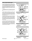
Main Information Screens
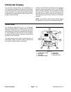
The two (2) I nfoCenter main information screens (Figs.
13 and 14) are d isplayed after the initial splash screen
has been displayed for several seconds. During normal
machine operation, the main information screens
provide machine information for the operator. Toggling
between the main information screens isdone by press-
ing the right button on the InfoCenter.
The main information screens can be used to monitor
enginecoolant temperature,fuel tanklevel,48 VDCbat-
teryvoltage, engineRPM, motor/generatortemperature
and traction speed range. The screens will also identify
if the parking brake is applied or if the cutting decks are
engaged.
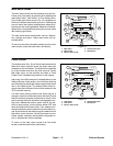
The main information screens will also display arrows
whenever the cutting deck sections are either raising
(up arrows) or lowering (down arrows).
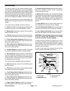
If controls are not selected properly to allow certain ma-
chine operations, the InfoCenter indicator light will illu-
minate and an advisory will be displayed on the
InfoCenter Display (see Advisories in the Troubleshoot-
ing sectionof thischapter). Typically, an advisorycan be
eliminated with a change in controls by the operator.
If an electrical machine fault occurs during machine op-
eration, the InfoCenter indicator light will blink to notify
the operator. Accessing the fault log is described below
in Faults Screen.
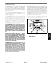
The main menu and additional information screens can
be accessed from the InfoCenter main information
screen by pressing and releasing the menu/back button
(left button) on the display. Information on the main
menu and menu item screens is included below.
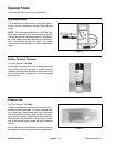
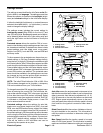
1. Parking brake applied
2. Traction speed range
3. Coolant temperature
4. Indicator light
5. Fuel gaug e
6. Right button
7. Middle button
8. Menu/back button
Figure 13
100
170
240
P
4
N
5
8
7
6
3
2
1
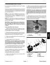
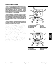
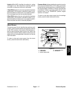
1. Engine RPM
2. Coolant temperature
3. Indicator light
4. Generator temperature
5. 48 VDC battery voltage
6. Right button
7. Middle button
8. Menu/back button
Figure 14
3
4
52.3V
1400
RPM
120
190
260
100
170
240
8
7
6
5
2
1
Electrical
System