


Reelmaster 5010- H Hydraulic SystemPage 4 - 73
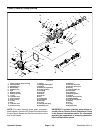
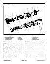
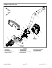
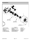
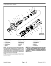
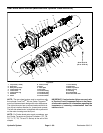
Disassembly (Fig. 64)
1. Remove hydraulic pump drive shaft from vehicle
(see Hydraulic Pump Drive Shaft in this section).
IMPORTANT: When placing yoke in vise, clamp
lightly on the solid part of the yoke to prevent yoke
damage. Also, the use of a vise with soft jaws is rec-
ommended.
2. Lightly clampdrive shaftyoke invise.Use twoscrew-
drivers to remove snap rings that secure bearings at the
inside of each yoke. Remove yoke from vise.
IMPORTANT: Yokes must be supported when re-
moving and installing bearings to prevent damage.
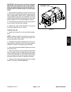
3. Use a press to remove cross and bearings from
yokes:
A. Place a small socket against one bearing and a
large socket against the yoke on the opposite side.
B. While supporting the large socket, apply pres-
sure on small socket to partially push the opposite
bearing into the large socket.
C. Remove yoke from press, grasp partially re-
moved bearing and tap on yoke to completely re-
move the bearing.
D. Repeat process for remaining bearings.
4. Thoroughly clean and inspect all components.
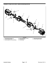
Assembly (Fig. 64)
1. To install new cross and bearings:
A. Apply a coating of greaseto bearing bores of end
yoke and shaft yoke. Also, apply grease to bearings
and seal of bearing assembly. Make sure that all
bearing rollers are properly seated in bearing cage.
B. Press one bearing partially into yoke.
IMPORTANT: Take care when installing cross
into bearing to avoid damaging bearing seal.
C. Carefully insert cross into bearing and yoke.
D. Hold crossin alignment andpress bearing inuntil
it hits the yoke.
E. Carefully place second bearing into yoke bore
and onto cross shaft. Press bearing into yoke.
F. Install snap rings to bearings to secure bearings
in place.
G. Repeat procedure for other yoke.
H. Greasecross untilgrease comesout ofallfour (4)
bearing cups.
2. Make su re that assembled joint moves without bind-
ing. Slight binding can usually be eliminated by lightly
rapping the yoke lugs with a soft faced hammer. If bind-
ing continues, disassemble joint to identify source of
binding.
3. Install hydraulic pump drive shaft to vehicle (see Hy-
draulic Pump Drive Shaft in this section).
Hydraulic
System