


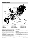
Reelmaster 5010- H Page 5 - 87 Electrical System
Disassembly
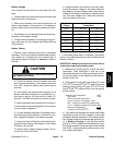
1. Park machine on level surface, lower cutting units,
stop engine, apply parking brake and remove key from
ignition switch.
2. Separate system components from the 48 VDC bat-
tery pack by unplugging the 48 VDC battery disconnect.
(see48 VDCBatteryDisconnectin theGeneralInforma-
tion section of this chapter). This will prevent unex-
pected 48 VDC system component operation.
3. Raise and support operator seat to access 48 VDC
power connections. If front jumper strap holders for
ground (negative) connections are to be accessed, re-
move operator floor plate from frame.
4. Label all wire connector locations for assembly pur-
poses.
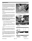
5. Disconnect electrical connections and remove com-
ponents as needed using Figures 88, 89 and 90 as
guides.
Assembly
1. Install all removed components and electrical con-
nections as needed using Figures 88, 89 and 90 as
guides. Use torque specifications identified in Figure 88
when installing fasteners.
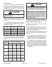
2. Apply Toro battery terminal protector (see Special
Tools in this c hapter) to all cable connectors to reduce
corrosion after cable connections are made. Make sure
that terminal boots and c onnection covers are posi-
tioned over all cable connections.
3. If operator floor plate was removed, secure floor
platetoframewithremovedfasteners.
4. Plug the 48 VDC battery disconnect back into the
socket when all electrical components have been in-
stalledtomachine.
5. Lower and secure operator seat.
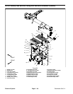
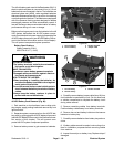
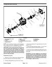
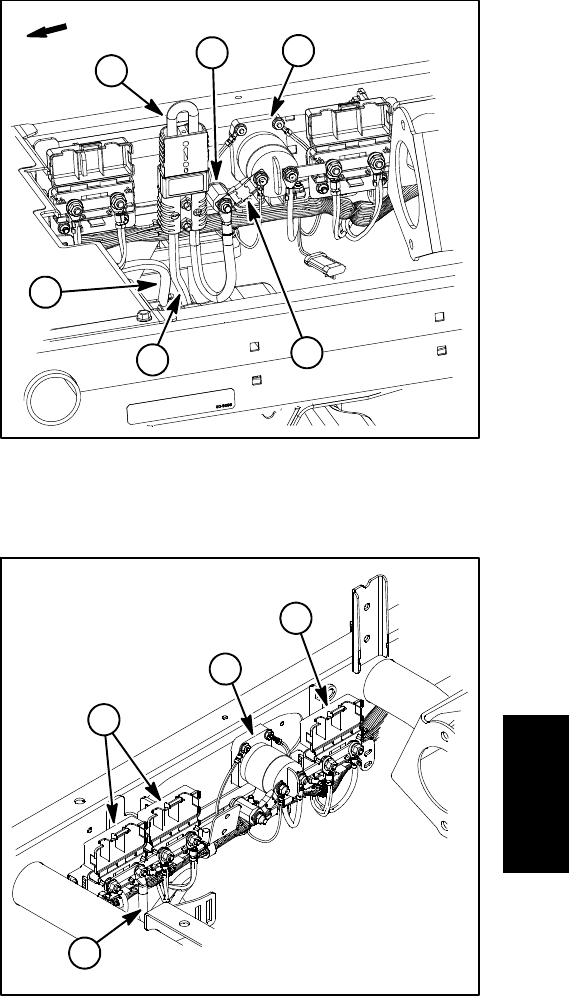
Figure 89
1. Main contactor
2. Positive battery cable
3. 48V battery disconnect
4. Negative battery cable
5. Isolator
6. Fuse (250A / 58V)
FRONT
2
3
5
6
1
4
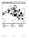
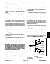
1. Main contactor
2. Positive connections
3. Ground connections
4. Neg battery cable
Figure 90
2
1
4
3
Electrical
System