


Reelmaster 5010- H Page 5 - 57 Electrical System
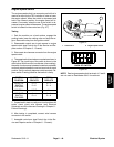
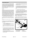
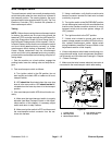
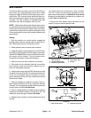
Mow/Transport Switch
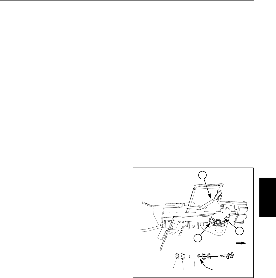
The mow/transportswitch isa normally closedproximity
switch that opens when the mow stop lever is placed in
the transport position. The sensing plate for the mow/
transportswitchisthe mowstoplever (Fig.49).The Toro
Electronic Controller (TEC) monitors the operation of
the mow/transport switch.
Testing
NOTE: Before disconnecting the mow/transport switch
for testing, the switch and its circuit wiring should be
tested as a TEC controller input with the InfoCenter Dis-
play (see Diagnostics Screen (Hi/Low Range item) in
the InfoCenter Display section of this chapter). If the In-
foCenter Display verifies that the mow/transport switch
and circuit wiring are functioning correctly, no further
mow/transport switch testing is necessary. If the Info-
Center Display determines that the mow/transport
switch and circuit wiring are not functioning correctly,
proceed with mow/transport switch testing using the fol-
lowing steps.
1. Park the machine on a level surface, engage the
parking brake, lower the cutting units and stop the en-
gine.
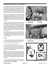
2. Test mow/transport switch as follows:
A. Turn ignition switch to the ON position (do not
start engine) and check LED on cable end of mow/
transport switch.
B. LED should be illuminated when the mow stop
lever is in the mow position. LED should not be illu-
minated when the mow stop lever is in the transport
position.
3. If the mow/transport switch LED did not function cor-
rectly:
A. Make sure that mow/transport switch is properly
adjusted (see Mow/Transport Switch in the Adjust-
ments section of this chapter). If necessary, adjust
switchandreturntostep2above.
B. Make sure ignition switch is OFF and disconnect
the mow/transport switch connector from the ma-
chinewireharness.
C. Using a multimeter, verify that the machine wire
harness connector terminal for black wire is closed
(continuity) to ground.
D. Turnignition switch tothe ON/PREHEAT position
(do not start engine)and verify with a multimeter that
machine wire harness connector terminal for mow/
transport switch pink wire has system voltage (12
VDC) present.
E. Turn ignition switch to the OFF position.
F. If black wire is closed to ground, pink wire has
system voltage present and switch LEDdid not func-
tion, replace mow/transport switch. Adjust switch
during installation (see Mow/Transport Switch in the
Adjustments section of this chapter).
4. If the mow/transport switch tests correctly and a cir-
cuit problem still exists,check wire harness (see Electri-
cal Schematic and Wire Harness Drawings in Chapter
9 - Foldout Drawings).
5. Make sure that wire harness electrical connector is
connected to the mow/transport switch after testing.
1. Traction pedal
2. Mow stop lever
3. Mow/transport switch
4. Lock washer (2 used)
5. Jam nut (2 used)
Figure 49
2
1
3
FRONT
LED location34
5
Electrical
System