


Reelmaster 5010- H Hydraulic SystemPage 4 - 69
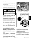
IMPORTANT: Mark the relative positions of the gear
teeth and the thrust plates so they can be reassem-
bledin thesame position.Do nottouch thegearsur-
faces as residue on hands may be corrosive to gear
finish.
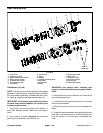
7. Remove the thrust plates and seals from each pump
section. Before removing each gear set, apply marking
dye to mating teeth to retain ”timing”. Pump efficiency
may be affected if the teeth are not installed in the same
position during assembly. Keep the parts for each pump
section together; do not mix parts between sections.
8. Clean all gear pump parts. Check allcomponents for
burrs, scoring, nicks and other damage.
9. Replace the entire pump assembly if component
parts are excessively worn or scored.
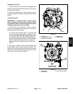
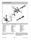
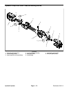
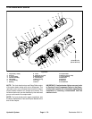
Assembly (Fig. 60)
1. Apply clean hydraulic oil to all parts before assem-
bling.
NOTE: Pressure and back - up seals fit in grooves ma-
chined into thrust plates. Square section seals fit in
grooves machined in body faces.
2. Assemble pump sections starting at front cover end.
Apply grease or petroleum jelly to new section seals to
hold them in position during gear pump assembly.
3. After pump has been assembled, tighten cap screws
and nuts by hand.
4. Place a small amount of clean hydraulic fluid into the
inlet of the gear pump and rotate the drive shaft away
fromtheinletonerevolution.Protecttheshaftif usingpli-
ers for turning the shaft. If any binding is noted, disas-
semble the pump and check for assembly problems.
5. Tighten the cap screws and nutsevenly ina crossing
patterntoatorqueof33 ft- lb (45 N-m).
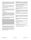
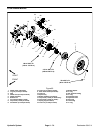
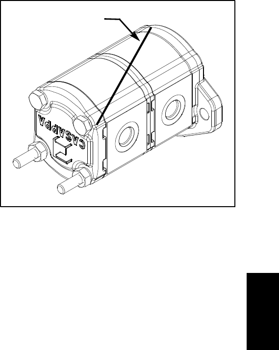
Figure 61
DIAGONAL LINE
Hydraulic
System