


Reelmaster 5010- H Hydraulic SystemPage 4 - 95
CAUTION
Before opening hydraulic system, operate all hy-
draulic controls to relieve system pressure and
avoid injury from pressurized hydraulic oil. See
Relieving HydraulicSystem Pressurein the Gen-
eral Information section of this chapter.
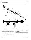
7. Disconnect hydraulic lines from steering control
valve. Allow lines to drain into a suitable container.
8. Put caps or plugs on disconnected lines and fittings
to prevent contamination.
9. Remove two (2) socket head screwsand flange nuts
that secure steering column to machine.
10.Remove steering column assembly with steering
control valve attached from machine.
11.Loosen andremove four(4) sockethead screwsthat
secure steering control valve to steering column.
12.Remove steering control valve from steering col-
umn.
13.If necessary, removefittings and O- ringsfrom steer-
ing control valve. Discard all removed O- rings.
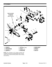
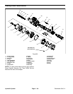
Installation (Fig. 77)
1. If fittings were removed, lubricate new O- rings with
clean hydraulic oil and install fittings to steering control
valve (see Hydraulic Fitting Installation in the General
Information section of this chapter).
2. Apply antiseize lubricant to s plines of steering con-
trol valve shaft.
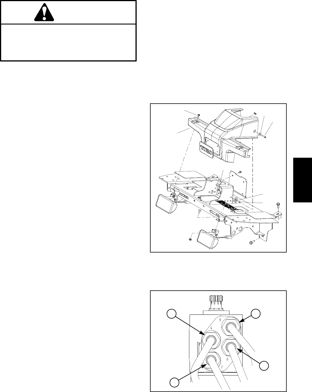
3. Slide steering control valve shaft into steering col-
umn universal joint. Position control valve with ports to-
ward front of machine. Secure steering control valve to
steering column with four (4) socket head screws. Hand
tighten screws in the sequence shown in Figure 77.
Then, using the same sequence, torque screws from 7
to 10 ft-lb (9.5 to 13.5 N-m).
4. Position steering column assembly to machine. Se-
cure steering column in place with two (2) socket head
screws and flange nuts at rear two mounting holes.
5. Remove caps and plugs from disconnected lines
and fittings.
6. Lubricate new O- rings and connect hydraulic lines
to fittings on steering control valve. Tighten connections
(see Hydraulic Hose and Tube Installation in the Gener-
al Information section of this chapter).
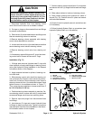
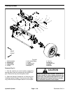
7. Position steering column brace (item 13) to machine
and secure with four (4) flange head screws and flange
nuts.
8. Slide rubber bellows to bottom of steering column.
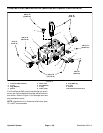
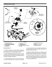
9. Place rubber bushings and spacers into holes of
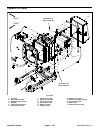
shroud (F ig. 78). Position shroud in place and secure
with removed fasteners.
10.Check oil level in hydraulic reservoir and add correct
oil if necessary.
11.Follow Hydraulic System Start- up procedures (see
Hydraulic System Start- up in this section).
1. Shroud
2. Screw (2 used)
3. Flat washer (2 used)
4. Phillips screw (2 used)
5. Lock nut (2 used)
6. Rubber bushing (2 used
)
7. Spacer (2 used)
Figure 78
4
3
1
2
5
6
7
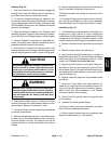
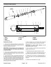
Figure 79
T
L
P
R
Hydraulic
System