


Reelmaster 5010- H Page 5 - 47 Electrical System
12 VDC S ystem Fuses
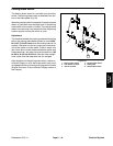
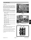
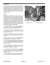
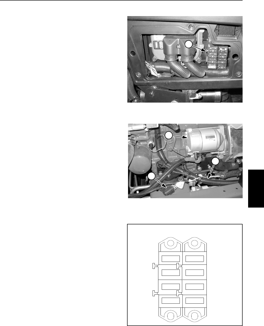
The fuse block is located b ehind the control arm access
cover (Fig. 32).
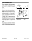
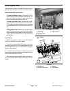
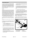
In addition to the 12 VDC fuses in the fuse block, a 2
Amp fuse is included in the wire harness to protect the
logic power circuit for the TEC controller. This fuse re-
sides in a fuse holder near the engine starter motor and
issecuredtothewireharnesswithacabletie(Fig.33).
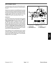
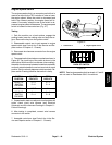
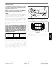
Identification and Function
The fuses are held in the fuse block. Use Figure 34 to
identify each individual fuse and its correct amperage.
Fuses for your Reelmaster have the following function:
Left Fuse 1 (15 Amp): Protects main and starter cir-
cuit power supply.
Left Fuse 2 (10 Amp): Protects main power supply.
Left Fuse 3 (10 Amp): Protects power supply for
headlights.
Left Fuse 4 (10 Amp): Protects power supply for
power point.
Right Fuse 1 (7.5 Amp): Protects power supply for
TEC controller outputs.
Right Fuse 2 (7.5 Amp): Protects power supply for
TEC controller outputs.
Right Fuse 3 (7.5 Amp): Protects power supply for
TEC controller outputs.
Right Fuse 4: Available for 20 Amp fuse used with
optional power operator seat.
Fuse Testing
1. Make sure that ignition switch is in the OFF position
and key is removed from ignition switch.
2. Remove control arm access cover to locate fuses.
3. Remove fuse(s) from the fuse block for testing. Fuse
should have continuity between fuse terminals.
4. After fuset esting iscompleted, installcontrol armac-
cess cover.
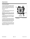
1. Fuse block
Figure 32
1
1. Fuse
2. Main wire harness
3. Starter motor
Figure 33
2
1
3
Figure 34
7.5A
4
3
2
1
10A
10A
10A
15A
LEFT RIGHT
4
3
2
1
7.5A
7.5A
Electrical
System