


Reelmaster 5010- HHydraulic System Page 4 - 84
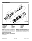
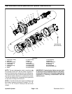
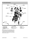
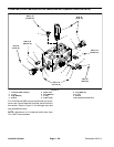
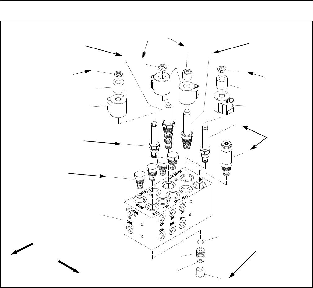
Lift Control M anifold Service
1. Lift control manifold
2. Check valve (4 used)
3. Solenoid valve (SV3)
4. Solenoid coil (2 used)
5. Solenoid coil spacer (2 used)
6. Nut (3 used)
7. Solenoid valve (SV2)
8. Solenoid coil (2 used)
9. Nut
10. Solenoid relief valve (SVRV)
11. Solenoid valve (SV1)
12. Relief valve (R7)
13. O-ring
14. Pilot piston (4 used)
15. O-ring
16. Hex plug (4 used)
Figure 71
FRONT
RIGHT
4
3
1
2
9
10
11
8
5
6
7
12
4
5
6
6
13
14
15
16
(33 N-m)
25 ft-lb
(27 N-m)
20 ft-lb
(27 N-m)
20 ft-lb
(101 N-m)
75 ft-lb
(27 N-m)
20 ft-lb
(33 N-m)
25 ft-lb
60 in- lb
(6.7 N-m)
60 in-lb
(6.7 N-m)
60 in-lb
(6.7 N-m)
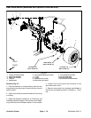
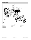
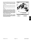
NOTE: Theports onthe lift controlmanifoldare marked
for easy identification of components. Example: P4 is
the gear pump connection port and SV2 is the location
for solenoid valve SV2 (see Hydraulic Schematic to
identify the function of the hydraulic lines and cartridge
valves at each port location).