


Reelmaster 5010- HPage 5 - 8Electrical System
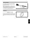
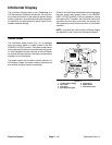
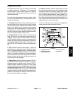
Generator Rotor Tool Set
Toro Part Number: TOR6029
The generator rotor tool set is required to remove and
install the rotor from the motor/generator housing. Tool
set includes base plate, threaded shaft and handle (Fig.
8).
NOTE: For motor/generator service procedures, see
Motor/Generator Assembly Service in the Service and
Repairs section of this chapter.
IMPORTANT: When working on the motor/genera-
tor, use a clean work space with a non- metal sur-
face. The motor/generator rotor includes very
powerful magnets.
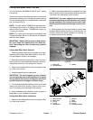
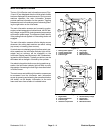
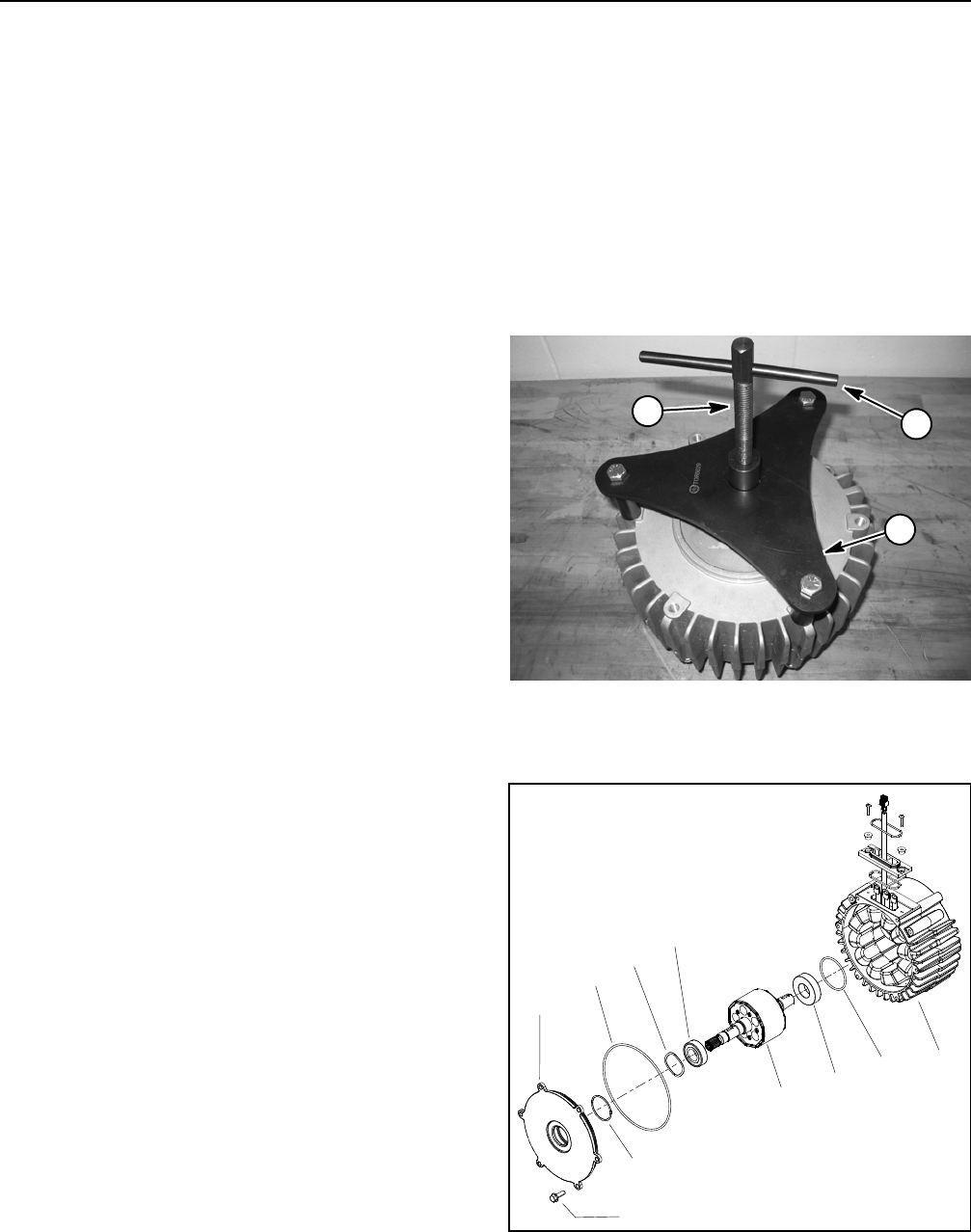
Motor/Generator Rotor Removal (Fig. 9)
1. Remove screws that secure motor/generator cover.
Do not remove cover from motor/generator assembly
because it will be removed with motor/generator rotor
during rotor removal.
2. Secure tool set base plate to motor/generator hous-
ing with three (3) 3/8” - 16 X 3” cap screws.
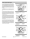
IMPORTANT: To prevent damage to motor/genera-
tor rotor shaft threads, position a thick washer or
spaceron end ofthe rotorshaft whenusing tool set.
3. Position thick w asheror spacer onthe endof themo-
tor/generatorrotor shaft. Installthreaded shaftinto base
plate and against washer or spacer on rotor shaft.
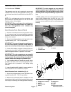
IMPORTANT: The rotor magnets are very powerful
andcan causethe rotorto shiftposition veryrapidly
duringremoval.Be cautiousduring rotorremovalto
prevent component damage or personal injury.
4. Turn threaded shaft with handle to remove motor/
generator rotor and cover from motor/generator hous-
ing. Support rotor to prevent it from falling during
removal.
5. Leave threaded shaft installed in same position in
tool base plate for rotor installation purposes.
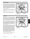
Motor/Generator Rotor Installation (Fig. 9)
1. Secure tool set base plate to motor/generator hous-
ing with three (3) 3/8” - 16 X 3” cap screws.
2. Make sure that threaded shaft is installed into tool
base plateso that theendofthethreaded shaft prevents
rotor body from entering the motor/generator housing.
IMPORTANT: The rotor magnets are very powerful
andcan causethe rotorto shiftposition veryrapidly
during installation. Be cautious during rotor instal-
lation topreventcomponent damageor personalin-
jury.
3. While guiding rotor into motor/generator housing,
slowly rotate threaded shaft to allow the r otor to be
drawn into the housing. Once rotor is fully installed into
housing, remove special tool set from motor/generator
housing.
1. Base plate
2. Threaded shaft
3. Handle
Figure 8
1
2
3
1. Housing/stator assembly
2. O-ring
3. Bearing
4. Rotor assembly
5. Bearing
6. Wave washer
7. O-ring
8. O-ring
9. Cover
10. Flange screw (6 used)
Figure 9
2
3
6
8
9
10
1
5
7
4