


Reelmaster 5010- HPage 5 - 2Electrical System
General Information
Operator’s Manual
The Operator’s Manual provides information regarding
the operation, general maintenance and maintenance
intervals for your Reelmaster machine. Refer to that
publicationf or additional information when servicing the
machine.
Electrical Drawings
The electrical schematic and wire harness drawings for
Reelmaster 5010- H machines are located in Chapter 9
- Foldout Drawings.
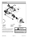
48 VDC Battery Disconnect
CAUTION
Before installing, removing or servicing compo-
nents in the 48 VDC system (e.g. cutting unit mo-
tors, motor/generator), separate the 48 VDC bat-
tery disconnect. This will prevent unexpected
operation of 48 VDC system components.
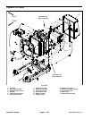
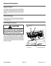
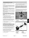
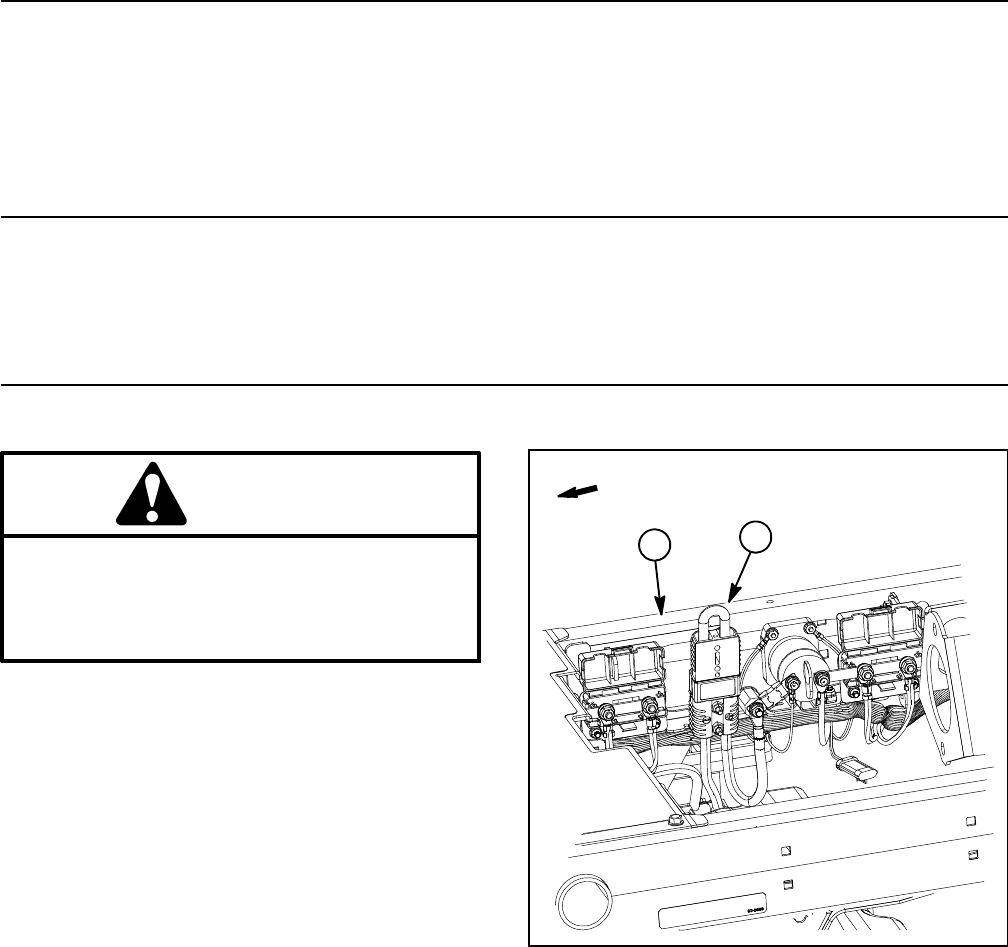
The 48 VDC battery disconnect is attached to the right
frame rail under the operator seat (Fig. 1). Unplug the
disconnect to make sure that 48 VDC components do
not operate unexpectedly. Apply dielectric grease to the
contact surfaces of the battery disconnect and plug the
battery disconnect back in after service to the 48 VDC
system is completed.
1. RH frame rail 2. 48V battery disconnect
Figure 1
2
1
FRONT