


Reelmaster 5010- H Hydraulic SystemPage 4 - 85
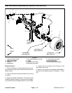
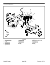
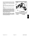
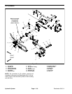
For lift control manifold service procedures, see Control
Manifold Cartridge Valve Service in t his section. Refer
to Figure 71 for cartridge valve installation torque. Refer
to Figures 71 and 72 for hydraulic fitting installation
torque values.
NOTE: Solenoid valves SV1 and SV2 on the lift control
manifolduse acoilspacer betweenthe solenoidcoiland
nut.
NOTE: Adjustment of Relief Valve (R7) is NOT recom-
mended.
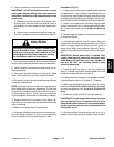
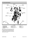
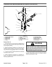
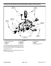
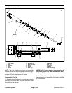
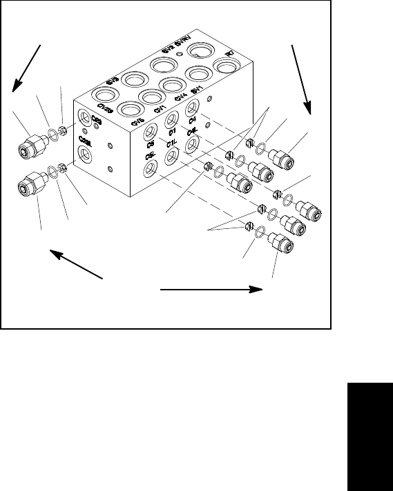
IMPORTANT: A flow control orifice is placed be-
neath severalof thehydraulic fittingson the liftcon-
trol manifold (Fig. 72). The lift manifold uses three
(3) different orifice sizes. If a fitting is removed from
the lift control manifold and an orifice is in the man -
ifold port, make sure to remove orifice and label its
position for assembly purposes.
IMPORTANT: When installing orifice in manifold
(Fig. 72), make sure that orifice is flat in the base of
the fittin g cavity. Manifold damage is possible if the
orifice is cocked in the cavity.
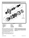
1. Fitting (2 used)
2. O-ring
3. Orifice (0.046)
4. Orifice (0.028)
5. Fitting (6 used)
6. Orifice (0.055)
Figure 72
4
1
2
5
3
1
2
3
4
2
2
6
6
5
(14 N-m)
10 ft-lb
(14 N-m)
10 ft-lb
(14 N-m)
10 ft-lb
Hydraulic
System