


Reelmaster 5010- HHydraulic System Page 4 - 68
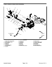
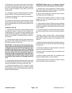
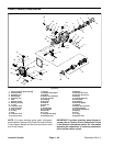
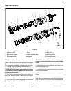
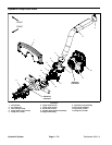
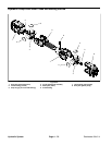
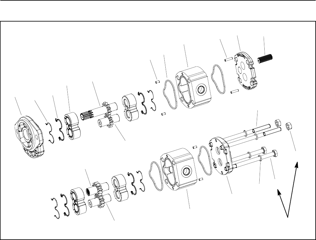
Gear Pump Service
1. Front cover
2. Dowel pin (4 used)
3. Square section seal (4 used)
4. Back-up seal (4 used)
5. Pressure seal (4 used)
6. Thrust plate (4 used)
7. Drive shaft
8. Driven gear
9. Body
10. Flange
11. Splined connecting shaft
12. Drive gear
13. Driven gear
14. Body
15. Dowel pin (2 used)
16. Rear cover
17. Washer (4 used)
18. Stud bolt (2 used)
19. Nut (2 used)
20. Cap screw ( 2 used)
Figure 60
33 ft-lb
(45 N-m)
4
1
2
9
10
11
8
5
6
7
12
3
13
14
17
18
15
16
19
20
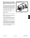
Disassembly (Fig. 60)
NOTE: The gearpump mustbe replaced as acomplete
assembly. Individual gears, housings and thrust plates
are not available separately. Disassemble gear pump
for cleaning, inspection and seal replacement only.
IMPORTANT: Keep bodies, gears and thrust plates
for each pump section together; do not mix parts
between pump sections.
1. Plug pump ports and thoroughly clean exterior of
pump with cleaning solvent. Make sure work area is
clean.
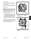
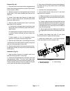
2. Use a marker to make a diagonal line across the
gear pump for assembly purposes (Fig. 61).
IMPORTANT: Use caution when clamping gear
pump ina vise toavoid distorting any pumpcompo-
nents.
3. Secure the front cover of the pump in a vise with the
drive shaft pointing down.
4. Loosen the two (2) cap screws and two (2) nuts that
secure pump assembly.
5. Remove pump from vise and remove loosened fas-
teners.
6. Supportt he pumpassemblyand gentlytap thepump
case with a soft face hammer to loosen the pump sec-
tions. Be careful to not drop parts or disengage gear
mesh.