Commands Listed in Alphabetical Order
Examples
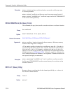
POWER:SWLOSS:
VCESAT 5
sets the VCEsat value to 5.0000.
POWER:SWLOSS:VCESAT ? might return :POWER: SWLOSS:VCEsat 2.0000
indicating that the VCEsat value is set to 2.0000.
POWer:TYPe
Sets or returns the power application measurement type.
Conditions
This command requires a DPO4PWR application m odule.
Group
Power
Syntax
POWer:TYPe {NONe|QUALity|SWITCHingloss |SOA
|HARMonics|RIPPle|MODULat ionanalysis|DESK ew}
POWer:TYPe?
Arguments
NONe Use to set the measurement type to None.
QUALity Use the power quality functions to obtain measurements and statistics
about the general power quality in your test circuit
SWITCHingloss Use the switching loss functions to obtain the power loss and
energy loss across the acquired waveform, in
cluding turn-on loss, turn-off loss,
conduction loss, and total loss. Typically, use these functions to char acterize
losses in power supply switching devices, as they switch on and off.
SOA Use the safe operating functions to obtain an X-Y display of the switching
device-under-test’s voltage and current. Also use them to perform a mask test of
the X-Y signal relative to the graphical X-Y description of the device specification
table. The s afe operating area is typically the voltage and current values that a
semiconductor can operate without damaging itself.
HARMonics Use the harmonics functions to obtain the frequency spectrum of the
source waveform and associated measurement values. Harmonic measurements
can help one perform in-depth troubleshooting of power quality problems.
RIPPle Use the ripple functions to obtain measurements and statistics for the
AC components of the acquired waveform. Ripples are often found on top of a
large DC signal.
MODULationanalysis Use the modulation functions to obtain a trend plot o f a
measurement value across the acquired waveform. This is useful for showing the
variations in the modulated switching signal.
DESKew Run the deskew procedure to match the delays through the probes.
Different p robes introduce different delays between the probe tip and the
2-314 MSO4000 and DPO4000 Series Programmer Manual


