


Reelmaster 7000 Hydraulic SystemPage 4 -- 65
Thec ooling fan circuittest shouldbe performedto make
sure that the engine cooling fan circuit has the correct
system pressure and fan speed.
Procedure for Cooling Fan Circuit Test
1. Make sure hydraulic oil is at normal operating tem-
peraturebyoperatingthemachineforapproximatelyten
(10) minutes. Make sure the hydraulic tank is full.
2. Parkmachine onalevel surfacewith thecuttingunits
lowered and off. Make sure engine is offand the parking
brake is applied.
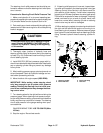
CAUTION
Prevent personal injury and/or damage to equip-
ment. Read all WARNINGS, CAUTIONS and Pre-
cautions for Hydraulic Testing at the beginning
of this section.
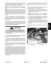
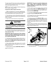
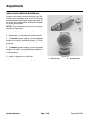
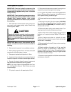
3. Raiseand support hood to gain access to fancontrol
manifold(Fig. 47).Connect a5,000 PSI(345 bar)gauge
with hydraulic hose attached to test fitting in port G2 on
rear of manifold.
4. After installing tester, start engine and run at idle
speed. Check for hydraulic leakage and correct before
proceeding with test.
5. Move throttle to full speed (2850 RPM).
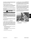
6. While monitoring the pressure gauge and using a
phototac to identify the cooling fan speed, disconnect
the wire harness connector (white/green and black
wires) from the proportional relief valve solenoid at fan
control manifold (port PRV). Both fan speed and pres-
sure should increase and stabilize after the solenoid is
disconnected.
PRESSURE GAUGE READING TO BE approxi-
mately 3000 PSI (207 bar)
PHOTOTAC (fan speed) READING TO BE approxi-
mately 2800 RPM
7. Stop engine and record test results.
8. If pressure rises to approximately 3000 PSI (207
bar) but fan speed is low, consider that the fan motor is
worn or damaged. If pressure and fan speed are both
low, consider that gear pump P4 is worn or damaged
(see Gear Pump P4 Flow Test in this section).
NOTE: Ifpressure andfan speed areboth lowand gear
pump P4 flow proves to be correct (see Gear Pump P4
Flow Test in this section), suspect that seals in fan con-
trol manifold are leaking or faulty (see Fan Control Man-
ifold Service in the Service and Repairs section of this
chapter) or that fan motor is worn or damaged.
9. When testing is complete, remove pressure gauge
from manifold fitting and reconnect wire harness to pro-
portionalreliefvalvesolenoid.Installdustcaptotestport
fitting. Lower and secure hood.
1. Fan control manifold
2. Test fitting (port G2)
3. PRV solenoid
Figure 47
2
1
3
Hydraulic
System