


Reelmaster 7000 Page 5 -- 7 Electrical System
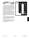
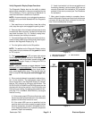
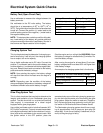
5. The “inputs displayed
” LED, on lower rightcolumn of
theDiagnostic Display, shouldbeilluminated. If“
outputs
displayed
”LEDis illuminated,pressthetogglebuttonon
the Diagnostic Display to change to “inputs displayed
”
LED.
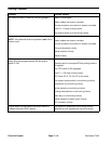
6. The Diagnostic Display will illuminate the LED
associatedwitheachoftheinputswhenthatinputswitch
is closed.Individually,change eachof theswitches from
open to closed (i.e., sit on seat, press traction pedal,
etc.), andnote thatthe appropriateLED on theDiagnos-
ticDisplay willilluminate whenthe correspondingswitch
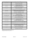
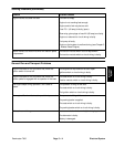
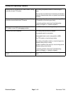
is closed. Repeat on each switch that is possible to be
changed by hand (see Diagnostic Display Inputs and
LED Operation chart on following page).
NOTE: When the Diagnostic Display is attached to the
wire harness connector and the ignition switch is in the
ON position, the input LED for hydraulic temp and cool-
anttemp shouldbe illuminated.If theharness connector
is disconnected from the sensor for either of these in-
puts, the appropriate LED should go off after a few sec-
ond delay. Then, if the harness connector is reattached
tothesensor,theinputLEDshouldagain illuminateafter
a few seconds.
7. If appropriate LED does not toggle on and off when
switch state is changed, check all wiring and connec-
tions to that switch and/or test switch (see Component
Testingin this chapter). Replace any defective switches
and repair any damaged wiring.
8. After input functions testing is complete, disconnect
the Diagnostic Display connector from the harnesscon-
nector and plug loop--back connector into wire harness.
Secure access plate to frame.
Figure 9
TEC
OVERLAY
Electrical
System