


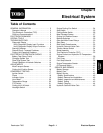
Reelmaster 7000Page 5 -- 2Electrical System
General Information
Operator’s Manual
The Operator’s Manual provides information regarding
the operation, general maintenance and maintenance
intervals for your Reelmastermachine. Refer to the Op-
erator’s Manual for additional information w hen servic-
ing the machine.
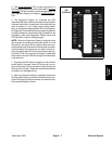
Toro Electronic Controller (TEC)
Reelmaster 7000machines usea single Toro Electronic
Controller (TEC) to manage machine electrical func-
tions.
The controller is microprocessor controlled that senses
the condition of various machine switches (inputs) and
directs electrical power to control appropriate machine
functions (outputs) based on the state of the inputs. The
status of inputsto the controllers as well asoutputs from
the controllers can be checked with the Diagnostic Dis-
play (see Special Tools).
Because of the solid state circuitry built into the Toro
Electronic Controller (TEC), there is no method to test
it directly. The TEC may be damaged if an attempt is
made to test it with an electrical test device, such as a
digital multimeter.
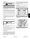
IMPORTANT: Before performing anywelding on the
machine, disconnect the battery cables from the
battery, disconnect the wire harness connectors
from the Toro Electronic Controller(s) and discon-
nect the terminal connector from the alternator to
prevent damage to the machine electrical system.
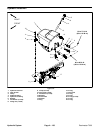
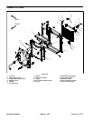
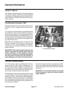
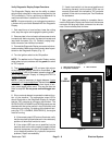
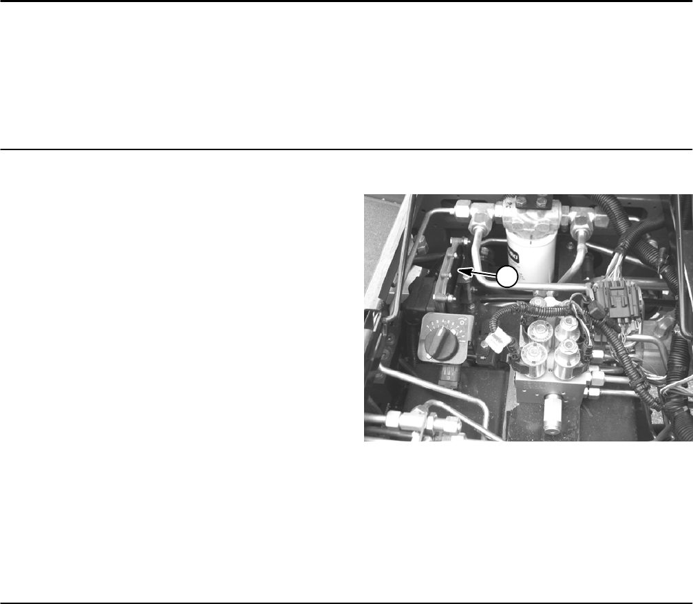
Figure 1
1
1. Toro Electronic Controller
CAN--bus Communications
The TEC controller used on the Reelmaster 7000 can
communicate with other electrical components on a
CAN--bus communication system. The CAN--bus sys-
tem reduces the number of electrical components and
connections used on the machine and allows the num-
ber of wires in the wire harness to be reduced.
CAN identifies the Controller Area Network that is used
on the Reelmaster. Two (2) specially designed, twisted
cables form the bus. These wires providethe data path-
ways between machine components. The engineering
term for these two (2) cables are CAN--high and CAN--
low.At the ends of the twisted pair of bus cables are 120
ohm termination resistors.
Each of the components that is controlled by the CAN--
buslinkonlyneedsfour(4)wirestooperateandcommu-
nicate to the system: CAN--high, CAN--low, B+ (power)
and ground.
IMPORTANT: The termination resistors at the ends
of the bus cables are required for proper electrical
system operation.