


Reelmaster 7000 Hydraulic SystemPage 4 -- 99
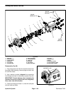
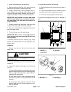
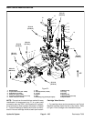
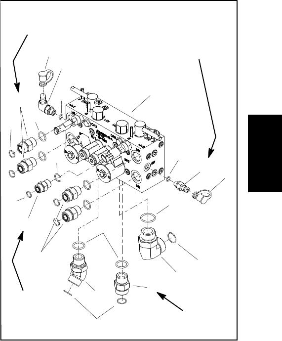
Removal (Fig. 72)
NOTE: The ports on the manifold are marked for easy
identification of components. Example: P1 is the gear
pump connection port (see Hydraulic Schematic in
Chapter 9 -- Foldout Drawings to identify the function of
the hydraulic lines and cartridge valves at each port).
1. Park machine on a level surface, lower cutting units,
stop engine, apply parking brake and remove key from
the ignition switch.
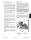
2. Read the General Precautions for Removing and
Installing Hydraulic System Components at the begin-
ning of the Service and Repairs section of this chapter.
3. Unlatch and raise hood.
4. To prevent contamination ofhydraulic system during
manifold removal,thoroughly clean exteriorof manifold.
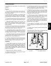
5. Label wire harness electrical connectors that attach
to manifold solenoid coils. Disconnect connectors from
the solenoid coils and backlap switches.
6. Disconnect hydraulic lines from manifold and put
caps or plugs on open hydraulic lines and fittings. Label
disconnected hydraulic lines for proper assembly.
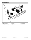
7. Remove hydraulic manifold from the frame using
Figure 72 as guide.
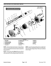
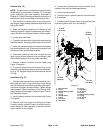
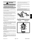
8. If hydraulic fittings are to be removed from control
manifold,mark fittingorientation toallow correctassem-
bly (Fig. 73). Remove fittings from manifold and discard
O--rings.
Installation (Fig. 72)
1. If fittings were removed from control manifold, lubri-
cate and place new O--rings onto fittings. Install fittings
into manifold portsusing marks made duringthe remov-
al process to properly orientate fittings. Tighten fittings
(see Hydraulic Fitting Installation in the General Infor-
mation section of this chapter). Refer to Figure 73for fit-
ting installation torque.
2. Install hydraulic manifold to the frame using Figure
72 as guide.
3. Remove caps and plugs from fittings and hoses.
Properly connect hydraulic lines to manifold (see Hy-
draulic Hose and Tube Installation in the General Infor-
mation section of this chapter).
4. Connect wire harness electrical connectors to the
solenoid valve coils and backlap switches.
5. Lower and secure hood.
6. Check oil level in hydraulic reservoir and add correct
oil if necessary.
7. Follow Hydraulic System Start--up procedures (see
Hydraulic System Start--up in this section).
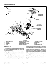
1. Mow manifold
2. O--ring
3. Straight fitting (8 used)
4. O--ring
5. O--ring
6. Straight fitting
7. O--ring
8. Dust cover
9. Test fitting
10. O--ring
11. Test fitting
12. 45
o
fitting
13. O--ring
14. Straight fitting (4 used)
15. O--ring
16. 90
o
fitting
17. O--ring
Figure 73
50 ft--lb
(68 N--m)
75 ft--lb
(101 N--m)
75 ft--lb
(101 N--m)
3
1
5
4
6
8
9
10
7
11
13
12
14
15
16
7
8
17
2
17
14
20 ft--lb
(27 N--m)
Hydraulic
System