


Reelmaster 7000 Page 5 -- 29 Electrical System
Backlap Switches
The backlap switches are normally open ball switches
that are in the normal, open state when the backlap lev-
ers are in the mow position. When a backlap lever is in
the backlap position, the switch closes. The backlap
switchesareattachedto thehydraulicmowcontrolman-
ifold located under the hood (Fig. 38). The Toro Elec-
tronic Controller (TEC) uses the backlap switches as
inputs.
Testing
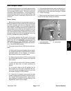
1. Park machine on a level surface, lower cutting units,
stop engine, engage parking brake and remove key
from the ignition switch.
2. Before disconnecting a backlap switch for testing,
the switch and its circuit wiring should be tested as a
TEC input with the Diagnostic Display (see Diagnostic
Display in the Troubleshooting section of this chapter).
If the Diagnostic Display verifies that the backlapswitch
and circuit wiring are functioning correctly, no further
switch testing is necessary. If, however, the Display de-
termines that the backlap switch and circuit wiring are
not functioning correctly, proceed with test.
3. Make sure ignition switch is in the OFF position.
4. Unlatch and raise hood to allow access to hydraulic
mow control manifold. Locate the backlap switch on the
front of the manifold. Disconnect the harness electrical
connector from the backlap switch.
5. Check the continuity of the switch by connecting a
multimeter (ohms setting) across the switch connector
terminals.
6. With the ignition switch in the OFF position, turn the
backlap lever to the backlapposition w hile watchingthe
multimeter.Continuityshouldbemadeasthe switchclo-
ses.
7. Turn the backlap lever to the mow position while
watchingthemultimeter.Continuityshould bebrokenas
the switch opens.
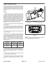
8. If backlap switch is faulty, replace s witch (Fig. 39).
9. If the backlap switch tests correctly and a c ircuit
problem still exists, check wire harness (see Electrical
Schematic and Wire Harness Drawings in Chapter 9 --
Foldout Drawings).
10.After testing is completed, connect harness electri-
cal connector to the backlap switch. Lower and secure
hood.
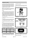
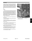
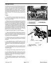
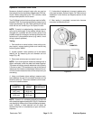
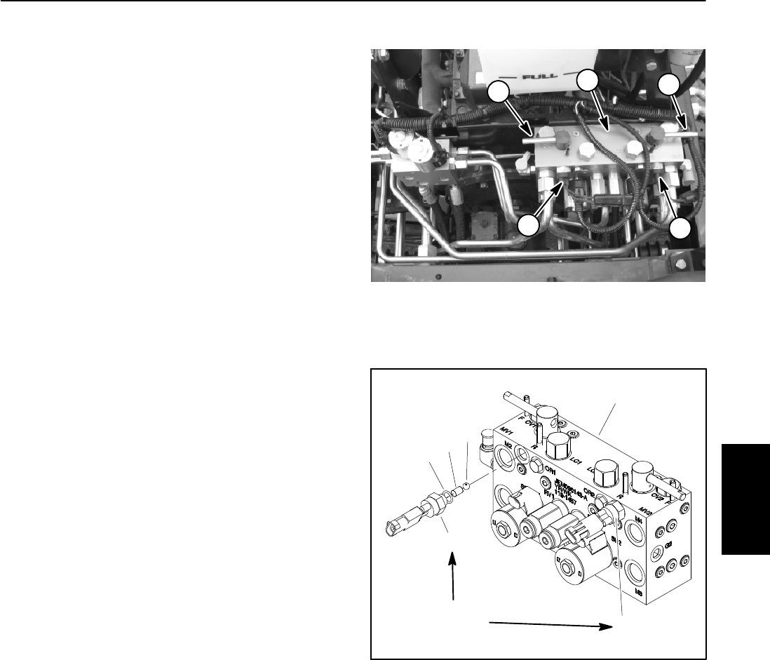
1. Mow control manifold
2. Front backlap lever
3. Front backlap switch
4. Rear backlap lever
5. Rear backlap switch
Figure 38
3
1
5
2
4
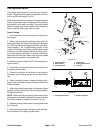
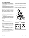
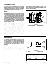
1. Mow control manifold
2. Backlap switch (2 used)
3. O--ring
4. Dowel
5. Ball
Figure 39
1
2
3
4
5
2
20 ft--lb
(27 N--m)
Electrical
System