


Reelmaster 7000Hydraulic System Page 4 -- 116
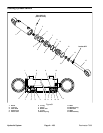
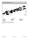
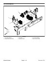
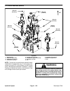
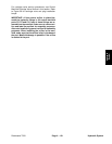
Fan Control Manifold Service
1. Manifold body
2. Zero leak plug (#6) (3 used)
3. Zero leak plug (#4) (2 used)
4. Check valve (port CV)
5. Flow divider cartridge (port FD)
6. Solenoid coil (2 used)
7. Nut
8. Solenoid valve (port S1)
9. Proportional relief cartridge (port TS)
10. Nut
Figure 87
7
4
6
3
2
1
5
9
8
2
2
6
25 ft--lb
(34 N--m)
25 ft--lb
(34 N--m)
20 ft--lb
(27 N--m)
60 in--lb
(6.8 N--m)
20 ft--lb
(27 N--m)
25 ft--lb
(34 N--m)
25 ft--lb
(34 N--m)
60 in--lb
(6.8 N--m)
1
10
UP
UP
50 ft--lb
(68 N--m)
NOTE: The ports on the fan control manifold are
marked for easy identification of components (e.g. STis
the supply to the steering control valve and FD is the
locationof the flowdivider cartridgevalve). SeeHydrau-
licSchematicin Chapter9 -- FoldoutDrawings toidentify
the function of the hydraulic lines and cartridge valves
at each port location.
For cartridge valve service procedures, see Control
Manifold Cartridge Valve Service in this section. Refer
to Figure 87 for cartridge valve and plug installation
torque.
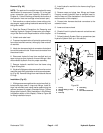
NOTE: The fan control manifold includes several zero
leak plugs. These plugs have a tapered sealing surface
on the plug head that is designed to resist vibration in-
duced plug loosening. The zero leak plugs also havean
O--ring as a secondary seal. If zero leak plug removal is
necessary, lightly rap the plug head using a punch and
hammer before using an allen wrench to remove the
plug:the impact willallow plugremoval with lesschance
of damage to the socket head of the plug.