


Reelmaster 7000 Hydraulic SystemPage 4 -- 75
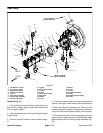
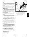
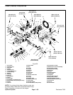
7. Support gear pump assembly to prevent it from fal-
ling.
8. Remove two (2) cap screws and washers securing
gear pumpto pistonpump. Removegear pump, coupler
(item 9), spacer (item 17) and O--rings (item 16) from
machine.
9. If hydraulic fittings are to be removed from gear
pump, mark fitting orientationto allow correct assembly.
Remove fittings from pump and discard O--rings.
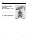
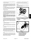
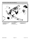
Installation (Fig. 51)
1. If fittings were removed from gear pump, lubricate
and place new O--rings onto fittings. Install fittings into
pump ports using marks made during the removal pro-
cess to properly orientate fittings. Tighten fittings (see
Hydraulic Fitting Installation in the General Information
section of this chapter).
2. Lubricatenew O--rings (item16) with cleanhydraulic
oil. Position O--rings on gear pump and pump spacer
flanges.
3. Slide coupler (item 9) onto the piston pump output
shaft.
4. Position pump spacer (item 17) to gear pump. Align
gear teeth and slide gear pump input shaft into c oupler.
Secure gear pump to piston pump with two (2) cap
screws and flat washers.
5. Remove caps and plugs from hydraulic hoses and
fittings. Install hoses to gear pump (see H ydraulic Hose
and Tube Installation in the General Information section
of this chapter).
6. Replace hydraulic filter and fill hydraulic reservoir
with new hydraulic oil.
7. Disconnect engine run solenoid electrical connector
to prevent engine from starting. Prime the hydraulic
pump by turning the ignition key switch to start and
crankingtheengineforten(10) seconds.Letstartercool
and then repeat cranking procedure again.
8. Connect engine run solenoid electrical connector,
start the engine and check for proper operation.
9. Properly fill hydraulic system (see Charge Hydraulic
System in this section).
10.Stop engine and check for hydraulic oil leaks. Check
hydraulic reservoir oil level.
11.Lower and secure seat.
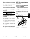
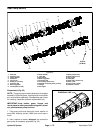
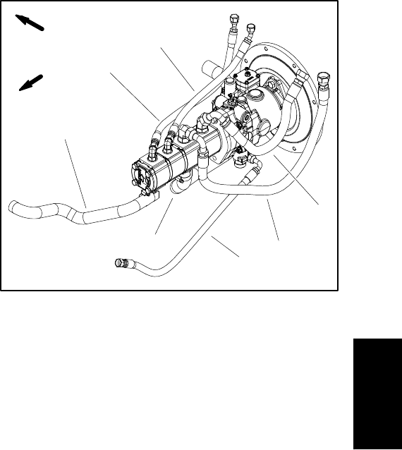
1. Supply hose to mow manifold P1 port
2. Supply hose to mow manifold P2 port
3. Supply hose to fan manifold P2 port
4. Supply hose to fan manifold P1 port
5. Suction hose from filter manifold
6. Suction hose from reservoir
7. Supply hose for charge circuit
Figure 52
4
5
1
2
3
6
7
FRONT
RIGHT
Hydraulic
System