


Reelmaster 7000
DPA Cutting Units
Page 8 -- 34
Roller Service
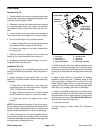
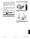
Disassembly (Fig. 36)
1. Remove bearing lock nut from each end of roller
shaft.
2. Loosely secure roller assembly in bench vise and
lightly tap one end of roller shaft until outer seals and
bearing are removed from opposite end of roller tube.
Removesecond setof outerseals and bearingfrom roll-
er tube by tapping on opposite end of shaft. Remove
shaft from roller tube.
3. Carefully remove inner seal from both ends of roller
tube taking care to not damage tube surfaces.
4. Discard removed s eals and bearings.
5. Cleanroller shaft andall surfaceson theinside of the
roller tube. Inspect components for wear or damage.
Also, carefully inspect seating surface and threads of
bearing lock nuts. Replace all damaged components.
Assembly (Fig. 36)
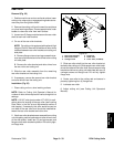
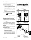
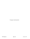
1. Install both inner seals into roller tube making sure
that seal lip (and garter s pring) faces end of tube. Use
inner sealtool (seeSpecial Tools) and softface hammer
to fullyseat seals againstr oller shoulder (Fig. 37).Apply
a small amount of grease around the lip of both inner
seals after installation.
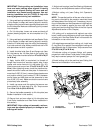
IMPORTANT: During assembly process, frequently
check that bearings rotate freely and do not bind. If
any binding is detected, consider component re-
moval and reinstallation.
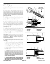
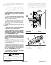
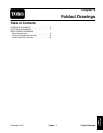
2. Install new bearing and outer seals into one end of
roller tube:
A. Positiona new bearinginto one endof roller tube.
Use bearing/outer seal tool (see Special Tools) with
as oft facehammer tofully seatbearing againstroller
shoulder (Fig. 38). After bearing installation, make
sure that it rotates freely with no binding.
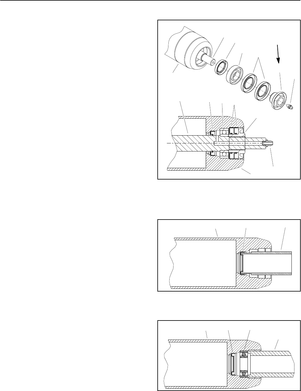
B. Apply a small amount of grease around the lip of
both outer seals.
C. Install first outer seal into roller tube making sure
that seal lip (and garter spring) faces end of tube.
Use bearing/outer seal tool (see Special Tools) and
soft face hammer to lightly seat seal against roller
shoulder (Fig. 39). Make sure that bearing still freely
rotates after seal installation.
D. Using the same process, install second outer
sealmakingsureto notcrushtheinstalledouter seal.
Again, make sure that bearing still freely rotates.
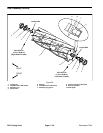
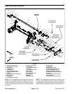
1. Roller tube
2. Roller shaft
3. Inner seal
4. Bearing
5. Outer seal
6. Bearing lock nut
7. Grease fitting
Figure 36
6
3
5
4
2
1
7
50 to 60 ft--lb
(68to81N--m)
6
3
5
4
2
1
7
1. Roller tube
2. Inner seal
3. Inner seal tool
Figure 37
321
1. Roller tube
2. Inner seal
3. Bearing
4. Bearing/outer seal tool
Figure 38
321
4