


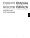
Reelmaster 7000 Hydraulic SystemPage 4 -- 79
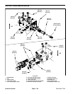
7. Remove gear pump from machine (see Gear Pump
Removal in this section).
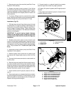
8. Support the piston pump to prevent it from falling
while removing two (2) cap screws and washers retain-
ing pump assembly to engine adapter plate. Carefully
pull pump assembly from adapter plate and raise it out
of the machine.
9. If hydraulic fittings are to be removed from piston
pump, mark fitting orientationto allow correct assembly.
Remove fittings from pump and discard O--rings.
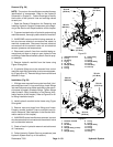
Installation (Fig. 55)
1. If fittings were removed from piston pump, lubricate
and place new O--rings onto fittings. Install fittings into
pump ports using marks made during the removal pro-
cess to properly orientate fittings. Tighten fittings (see
Hydraulic Fitting Installation in the General Information
section of this chapter).
IMPORTANT: To prevent spring coupler damage,
make sure that piston pump is properly supported
anddoes notputsideload intocouplerduring pump
installation.
2. Carefully lower piston pump into the machine and
position it to the engine adapter plate. Support pump to
prevent it from fallingwhile installing two (2) cap screws
and washers securing piston pump to engine adapter
plate. Torque screws from 77 to 93 ft--lb (105 to 126
N--m).
3. Install gear pump to piston pump (see Gear Pump
Installation in this section).
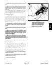
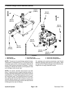
4. Position traction rod to control arm on piston pump
and secure with flange head screw and lock nut (Fig.
56).
5. Connectwire harnessconnector toneutral switch on
traction pump.
6. Remove plugs and caps from disconnected hydrau-
lic hoses and open ports of the pump assembly. Install
fittings and hoses to correct location on gear and piston
pumps (see Hydraulic Hose and Tube Installation in the
General Information section of this chapter).
7. Install new filter and fill hydraulic reservoir with cor-
rect oil.
8. Disconnect engine run solenoid electrical connector
to prevent engine from starting.Prime pumps by turning
ignition key switch to crank engine forten (10)seconds.
Repeat cranking procedure again.
9. Connect engine run solenoid electrical connector,
start the engine and check for proper operation.
10.Properly fill hydraulic system (see Charge Hydraulic
System).
11.Stop engine and check for hydraulic oil leaks. Check
hydraulic reservoir oil level.
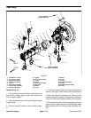
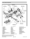
1. Piston pump
2. Neutral switch
3. Traction rod
4. Flange head screw
5. Lock nut
Figure 56
1
2
3
4
5
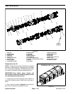
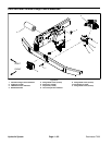
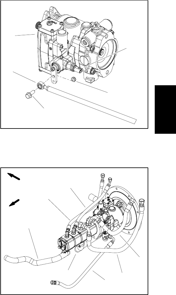
1. Supply hose to mow manifold P1 port
2. Supply hose to mow manifold P2 port
3. Supply hose to fan manifold P2 port
4. Supply hose to fan manifold P1 port
5. Suction hose from filter manifold
6. Suction hose from reservoir
7. Supply hose for charge circuit
Figure 57
4
5
1
2
3
6
7
FRONT
RIGHT
Hydraulic
System