Reelmaster 7000Hydraulic System Page 4 -- 76
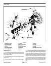
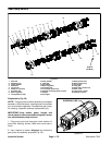
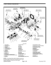
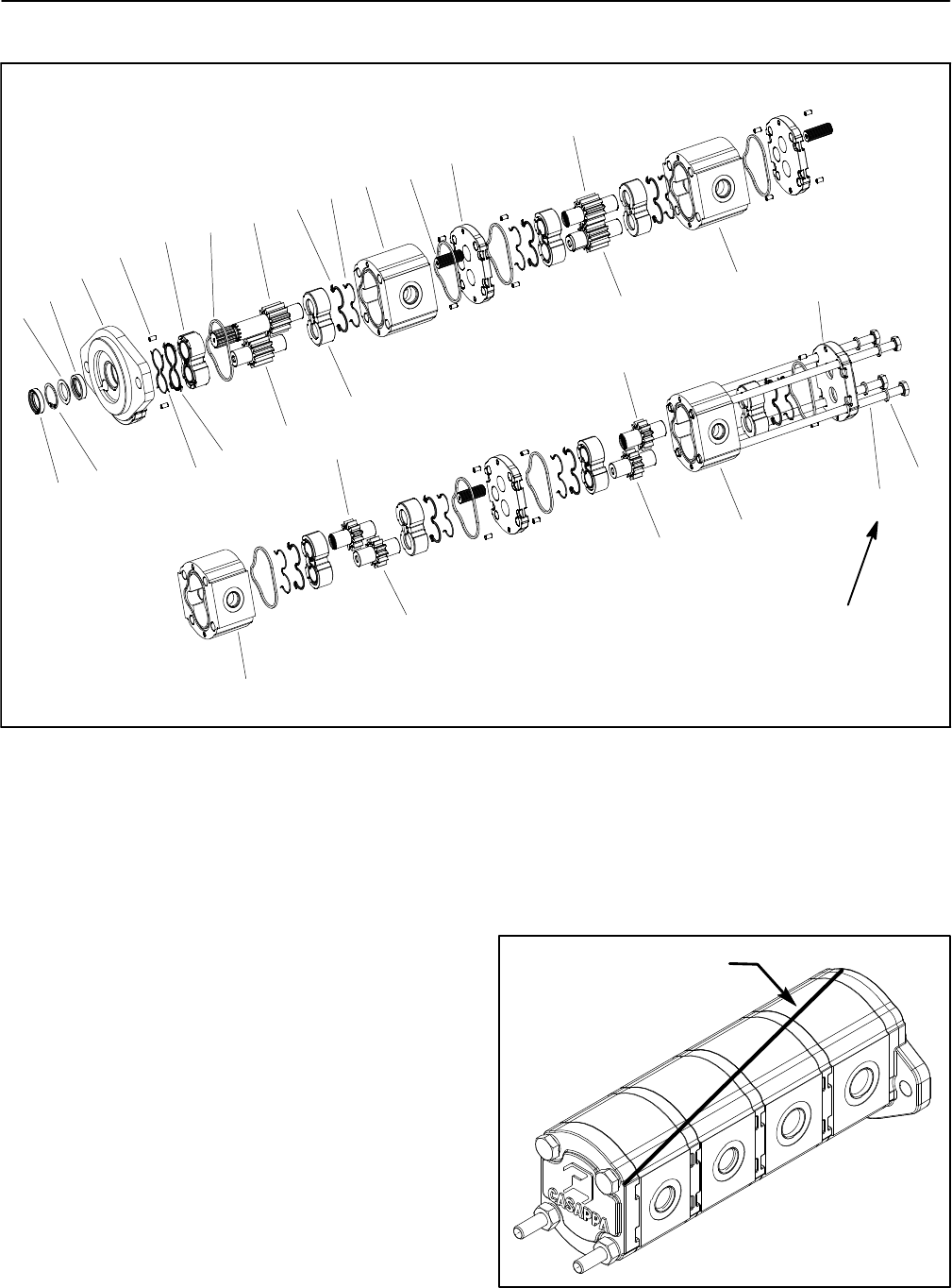
Gear Pump Service
1. Dust seal
2. Retaining ring
3. Flange washer
4. Shaft seal
5. Front cover
6. Dowel pin (16 used)
7. Pressure seal
8. Back--up gasket
9. Thrust plate (8 used)
10. Seal (8 used)
11. Idler gear
12. Drive shaft
13. Back--up gasket
14. Pressure seal
15. Front body (section P1)
16. Splined connecting shaft (3 used)
17. Flange
18. Drive gear
19. Body (section P2)
20. Body (section P3)
21. Drive gear
22. Idler gear
23. Rear body (section P4)
24. Rear cover
25. Cap screw (4 used)
26. Washer (4 used)
Figure 53
10
11
8
15
5
3
19
20
21
22
23
24
9
7
25
26
6
1
2
16
17
18
4
14
13
12
9
33 ft--lb
(45 N--m)
11
22
21
Disassembly (Fig. 53)
NOTE: Thegear pumpmustbe replacedas acomplete
assembly. Individual gears, housings and thrust plates
are not available separately. Disassemble gear pump
for cleaning, inspection and seal replacement only.
IMPORTANT: Keep bodies, gears, flanges and
thrustplates foreachpump sectiontogether;do not
mix parts between pump sections.
1. Plug pump ports and thoroughly clean exterior of
pump with cleaning solvent. Make sure work area is
clean.
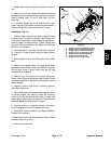
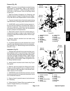
2. Use a marker to make a diagonal line across the
gear pump for assembly purposes (Fig. 54).
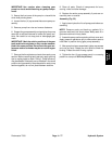
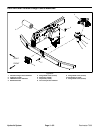
Figure 54
DIAGONAL LINE


