


Reelmaster 7000
DPA Cutting Units
Page 8 -- 24
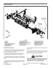
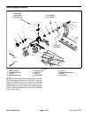
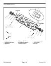
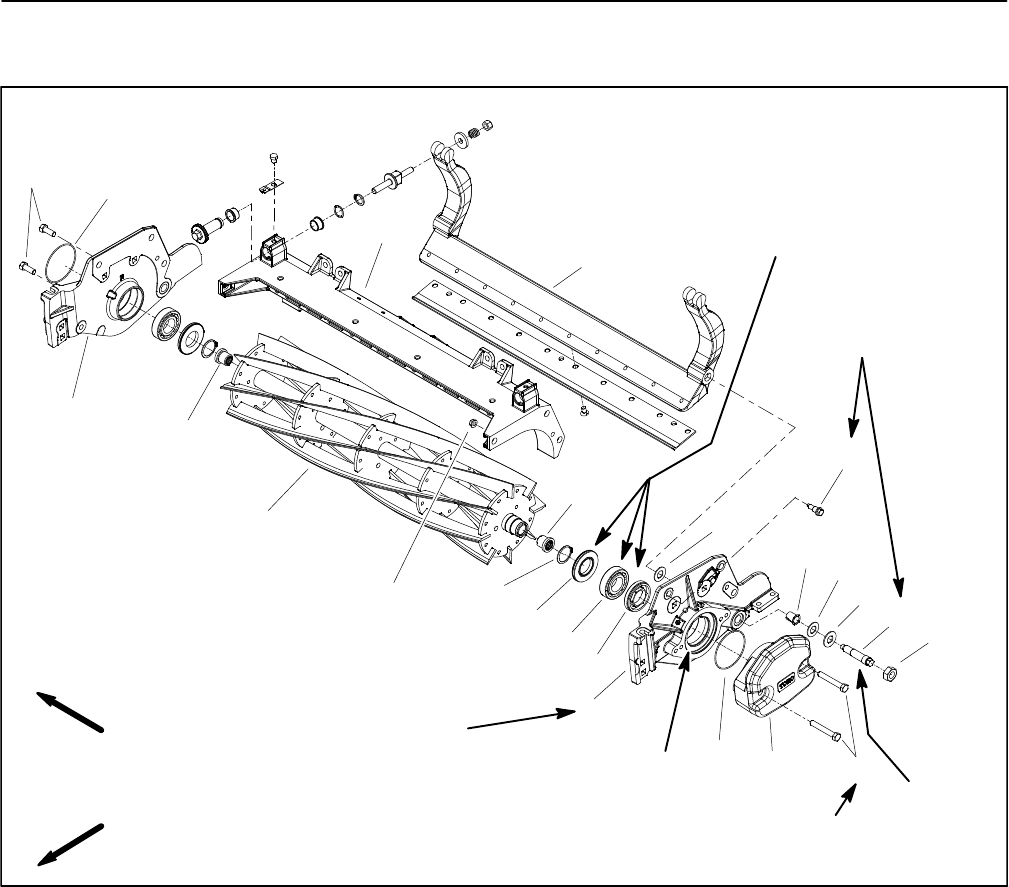
Reel Assembly Removal and Installation
1. Bedbar assembly
2. Flange nut (3 used per side plate)
3. Flange bushing (2 used)
4. Plastic washer (4 used)
5. Metal washer (2 used)
6. Bedbar pivot bolt (2 used)
7. Lock nut (2 used)
8. Shoulder bolt (3 used per side plate)
9. LH side plate
10. Weight
11. Cap screw (2 used)
12. O--ring
13. Cutting reel
14. Spline insert (LH thread)
15. RH side plate
16. Spline insert (RH thread)
17. Retaining ring (2 used)
18. Grease seal (2 used)
19. Bearing (2 used)
20. Bearing adjuster nut
21. Cap screw (2 used)
22. Cutting unit frame
Figure 29
Antiseize
Lubricant
FRONT
RIGHT
Grease OD surface
See text for
tightening
procedure
Grease bore
and threads
27 to 33 ft--lb
(37to44N--m)
27 to 33 ft--lb
(37to44N--m)
6
7
8
9
1
4
2
5
3
4
10
11
12
13
15
16
17
18
19
14
20
21
12
22
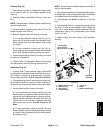
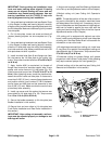
NOTE: This section provides the procedure for remov-
ing and installing the cutting reel assembly (cuttingreel,
spline inserts, grease seals and bearings) from the cut-
ting unit.
NOTE: RefertoReelAssemblyServicelaterinthissec-
tion for information on replacing cutting reel grease
seals, bearings and spline inserts.
NOTE: Removal of the cutting reel requires removal of
the left side plate from the cutting unit frame. The right
side plate does not have to be removed from the frame.
NOTE: Figure29showscomponents whenthehydrau-
lic reel motor is on the right side of the cutting unit.