


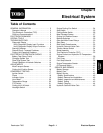

Reelmaster 7000Page 5 -- 6Electrical System
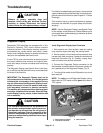
Troubleshooting
CAUTION
Remove all jewelry, especially rings and
watches, before doing any electrical trouble-
shooting or testing. Disconnect the battery
cables unless the test requires battery voltage.
For effective troubleshooting and repairs,there must be
a good understandingof the electrical circuits and com-
ponents used on this machine (see Chapter9 -- Foldout
Drawings).
If the machine has any interlock s witches by--passed,
reconnect the switches for proper safety and trouble-
shooting.
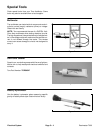
NOTE: Use the Diagnostic Display (see Special Tools
in this chapter) to test Electronic Control Module inputs
and outputs whentroubleshooting an electrical problem
on your Reelmaster.
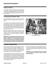
Diagnostic Display
Reelmaster 7000 machines are equipped with a Toro
Electronic Controller (TEC) which controls machine
electrical functions. The controller monitors various in-
put switches (e.g. ignition switch, seat switch, neutral
switch) and energizes outputs to actuate solenoids or
relays for the requested machine function.
For the TEC to control the machine as desired, each of
the inputs (switches and sensors) and outputs (sole-
noids and relays) must be connected and functioning
properly.
The Diagnostic Display (see Special Tools in this chap-
ter)isa tooltohelpthetechnicianverify correctelectrical
functions of the machine.
IMPORTANT: The Diagnostic Display must not be
left connected to the machine. It is not designed to
withstand the environment of the machine’s every
dayuse. Whenuseof theDiagnostic Displayiscom-
pleted, disconnect it from the machine and recon-
nect loop--back connector to harness connector.
The machine will not operate without the loop--back
connector installed on the harness. Store the Diag-
nostic Display in a dry, secure, indoor location and
not on machine.
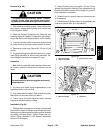
CAUTION
The interlock switches are for the protection of
the operator and bystanders and to ensure cor-
rect operation of the machine. Do not bypass or
disconnect switches. Check the operation of the
interlockswitches dailyforproperoperation. Re-
place any malfunctioning switches before oper-
ating the machine.
Verify Diagnostic Display Input Functions
1. Park machine on a level surface, lower the cutting
units, stop the engine and apply the parking brake.
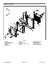
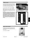
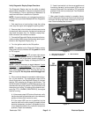
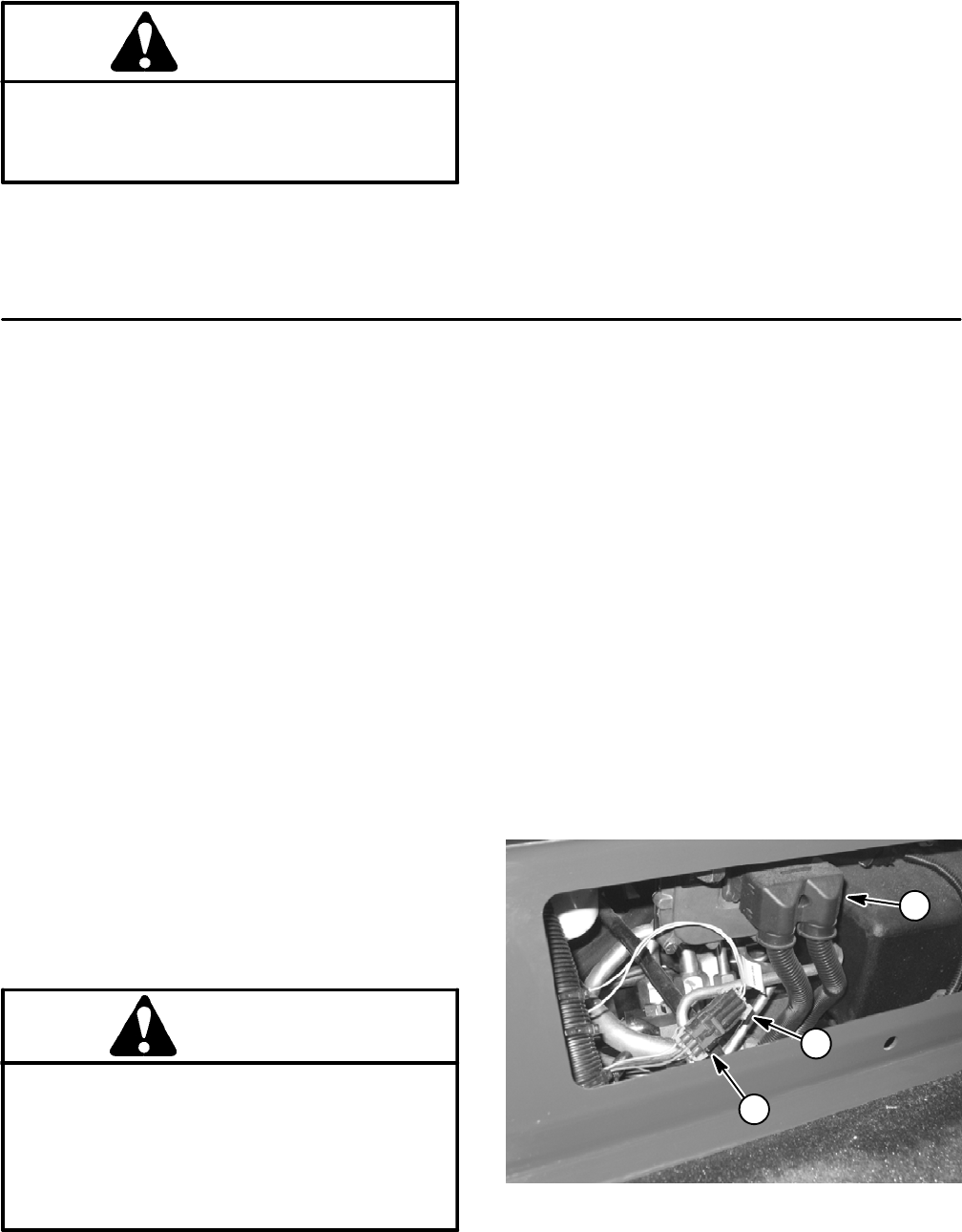
2. Remove plate in front of seat to allow access to wire
harness loop--back connector.Locate wire harness and
loop--back connector (Fig. 8). Carefully unplug loop--
back connector from harness connector.
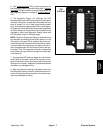
3. Connect the Diagnostic Display connector to the
wire harness connector. Make sure correct overlay de-
cal is positioned on the Diagnostic Display (Fig. 9).
4. Turnthe ignition switch to theON position, but do not
start machine.
NOTE: The red text on the D iagnostic Display overlay
decal refers to TEC inputs and the green text refers to
TEC outputs.
1. Wire harness connector
2. Loop--back connector
3. TEC controller
Figure 8
1
2
3