


Reelmaster 7000
DPA Cutting Units
Page 8 -- 25
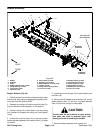
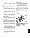
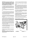
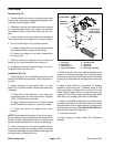
Reel Assembly Removal (Fig. 29)
1. Positionmachine on a clean andlevel surface, lower
cutting units,stop engine, engage parkingbrake and re-
move key from the ignition switch.
2. Remove the cutting unitfrom the machineand place
ona flatworkarea (seeCuttingUnit RemovalandInstal-
lation in this section).
3. If cutting unit is equipped with a weight on LH side
plate (as shown in Figure 29), remove the two (2) cap
screws securing the weight to the side plate. Remove
weightfromthecuttingunit.Remove anddiscardO--ring
from weight.
4. If cutting unit is equipped with an optional rear roller
brush, remove components for those options from left
hand side plate of cutting unit. See Rear Roller Brush in
the Service and Repairs section of this chapter for infor-
mation on rear roller brush.
5. Remove the bedbar pivot bolt (item 6) and washers
from the LH side plate.
6. Loosenfasteners that secure frontand rear rollersto
LHsideplate(see FrontRollerRemovalandRearRoller
Removal in this section).
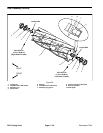
7. Remove cap screw and flat washer that secure rear
grass shield to LH side plate (Fig. 30).
8. Remove flange head screw that secures support
tube, frame spacer and carrier frame to LH side plate
(Fig. 30).
NOTE: Thereel bearingsand grease sealsare pressfit
on the cutting reel shaft and should remain on the reel
when removing the LH side plate.
9. Removeshoulderbolts(item8) andflangenuts(item
24) that secure the LH side plate to the cutting unit
frame.Removethe LHsideplate fromthereelshaft, roll-
ers, bedbar and cutting unit frame.
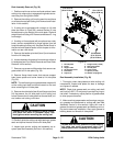
CAUTION
Contact with the reel, bedknife or other cutting
unit parts can result in personal injury. Use
heavy gloves when removing the cutting reel.
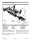
10.Carefully slide the cutting reel with bearings, grease
seals and splined inserts from the RH side plate.
11.Inspect and service cutting reel assembly as re-
quired (see Reel Assembly Service in this section).
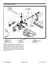
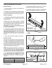
Figure 30
15 to 19 ft--lb
(20to25N--m)
15 to 19 ft--lb
(20to25N--m)
27 to 33 ft--lb
(37to44N--m)
Loctite #242
3
7
6
5
9
8
2
4
1
1. RH side plate
2. Frame
3. Support tube
4. Socket head screw
5. Flat washer
6. Cap screw
7. Flange screw (2 used)
8. Rear grass shield
9. LH side plate
10. Carrier frame
11. Spacer (2 used)
12. Washer (if equipped)
10
11
12
Reel Assembly Installation (Fig. 29)
1. Thoroughly clean side plates and other cutting unit
components. Inspect side plates for wear or damage
and replace if needed.
NOTE: Check that grease seals on cutting reel shaft
are flush to0.060” (1.5 mm) away from retainingring on
reel shaft. If necessary, adjust position of grease seals
to allow proper clearance.
2. Make sure that grease s eals and bearings are prop-
erly greased and positioned on cutting reel (see Reel
Assembly Service in this section). Apply thin coat of
grease to outside of grease seals and bearings on cut-
ting reel to ease reel installation. Also, apply grease to
bearing bores and threads in side plates.
CAUTION
Contact with the reel, bedknife or other cutting
unit parts can result in personal injury. Use
heavy gloves when installing the cutting reel.
DPA Cutting
Units