


Reelmaster 7000Page 7 -- 10Chassis
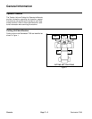
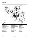
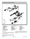
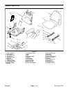
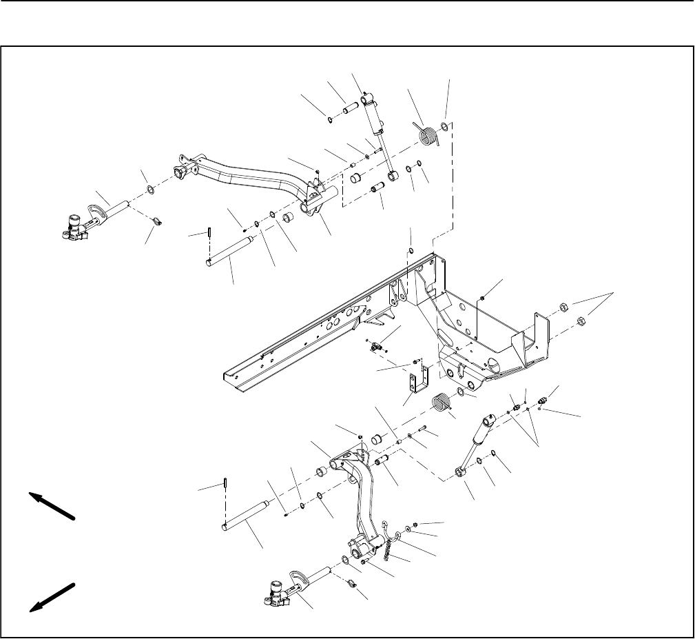
Lift Arms for Rear Cutting Units (#2 and #3)
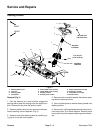
Figure 9
FRONT
RIGHT
1
2
4
5
6
7
8
9
10
11
14
15
16
17
19
20
21
22
23
24
25
26
7
8
16
26
16
16
32
17
13
11
11
11
11
32
5
6
26
26
24
22
25
23
11
12
12
3
27
28
29
30
18
31
33
31
1. Flange nut (2 used)
2. Bulkhead bracket
3. Hydraulic tee fitting
4. Flange head screw (2 used)
5. Slotted roll pin
6. Pivot pin
7. Pivot yoke
8. Lynch pin
9. Lift arm (cutting unit #2)
10. Lift arm (cutting unit #3)
11. Retaining ring (2 per pin)
12. Lift cylinder (cutting units #2 and #3)
13. Lock nut
14. Straight hydraulic fitting
15. Cylinder pin
16. Thrust washer
17. Cylinder pin
18. Flange head screw (2 per hoop)
19. 90
o
hydraulic fitting
20. LH torsion spring
21. RH torsion spring
22. Spacer
23. Cap screw
24. Lock nut
25. Flat washer
26. Washer (2 per pin)
27. Washer (2 per hoop)
28. Chain hoop
29. Flange nut (2 per hoop)
30. Lift chain
31. O--ring
32. Grease fitting
33. O--ring
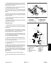
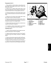
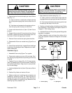
Removal (Fig. 9)
1. Park machine on a level surface, lower cutting units,
stop engine, engage parking brake and remove key
from the ignition switch.
2. Remove cutting unit from lift arm (see Cutting Unit
Removal in the Service and Repairs section of Chapter
8 -- DPA Cutting Units).
3. Remove one (1) retaining ring and washer from the
cylinder pin (item 17). Remove cylinder pin from the lift
arm and cylinder rod clevis which will free lift cylinder
from lift arm.