


Reelmaster 7000Hydraulic System Page 4 -- 118
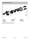
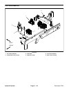
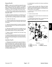
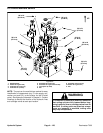
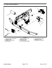
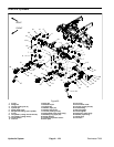
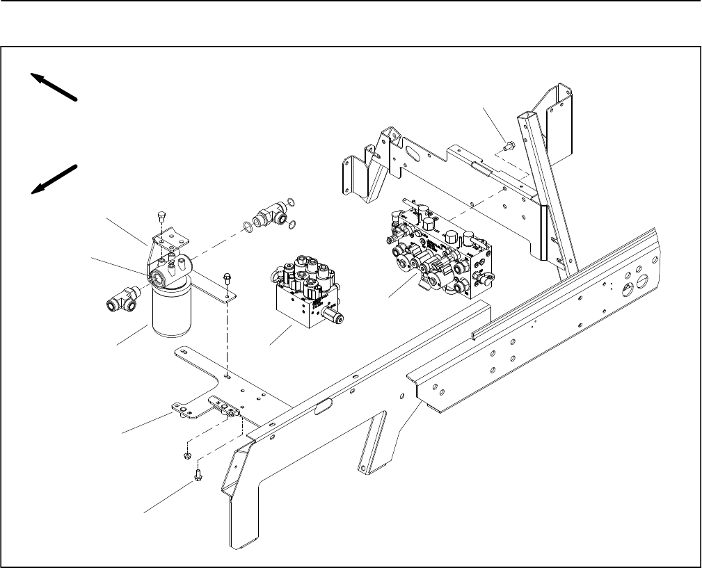
Lift Control Manifold
1. Lift control manifold
2. Filter mount bracket
3. Filter head
4. Hydraulic oil filter
5. Valve mount bracket
6. Flange head screw (2 used)
7. Mow control manifold
Figure 88
FRONT
RIGHT
3
4
7
1
6
2
5
8
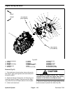
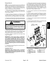
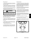
Removal (Fig. 88)
NOTE: The ports on the manifold are marked for easy
identification of components. Example: P is the supply
connection port (see Hydraulic Schematic in Chapter 9
-- FoldoutDrawings toidentifythefunctionof thehydrau-
lic lines and cartridge valves at each port).
1. Park machine on a level surface, lower cutting units,
stop engine, apply parking brake and remove key from
the ignition switch.
IMPORTANT: To prevent unexpected cutting unit
lowering, make sure that cutting units are fully low-
ered before loosening hydraulic lines from lift man-
ifold.
2. Read the General Precautions for Removing and
Installing Hydraulic System Components at the begin-
ning of the Service and Repairs section of this chapter.
3. Unlatch and raise hood.
4. To prevent contamination ofhydraulic system during
manifold removal,thoroughly clean exteriorof manifold.
5. Label wire harness electrical connectors that attach
to manifold solenoid coils. Disconnect wire harness
electrical connectors from the solenoid valve coils.