


Reelmaster 7000 Hydraulic SystemPage 4 -- 49
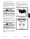
Procedure for Mow Circuit Pressure Test
1. Make sure hydraulic oil is at normal operating tem-
peraturebyoperatingthemachineforapproximatelyten
(10) minutes. Make sure the hydraulic tank is full.
2. Parkmachine onalevel surfacewith thecuttingunits
lowered and off. Make sure engine is offand the parking
brake is engaged.
3. Raise hood toallow access to mow control manifold.
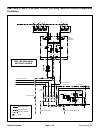
CAUTION
Prevent personal injury and/or damage to equip-
ment. Read all WARNINGS, CAUTIONS and Pre-
cautions for Hydraulic Testing at the beginning
of this section.
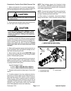
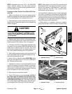
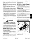
4. Install 5000 PSI (350 bar) pressure gauge with hy-
draulic hose attached to mow control manifold test port
for the mow circuit (front or rear cutting units) to be
tested(Fig. 37).Manifold testport G1should beusedfor
the front reel circuit and G2 should be used for the rear
reel circuit.
5. After installing pressure gauge, start engine and run
at low idle speed. Check for hydraulic leakage and cor-
rect before proceeding with test.
6. Move throttle to high idle speed (2850 RPM).Make
sure that mow speed limiter is in the mow (4WD) posi-
tion. Release parking brake.
CAUTION
Cutting reel blades will rotatewhen loweredwith
PTO switch in ON position. Keep away from cut-
ting units during test to prevent personal injury
from rotating reel blades. Do not stand in front of
the machine during test.
7. With seat occupied, engage the mow circuit. Watch
pressure gauge carefully while mowing with the ma-
chine.
8. Mow circuit pressure should be from 1000 to 3000
PSI (69 to 207 bar) and will vary depending on mowing
conditions.
9. Disengage cutting units and shut off engine. Record
test results.
10.After testingiscomplete,disconnect pressuregauge
frommanifold testport.Install dustcap totestport fitting.
If necessary, repeat test for other mow circuit.
11.Lowerandsecure hoodafterallmow circuitpressure
testing is completed.
1. Test port G1 (front cutting units)
2. Test port G3 (rear cutting units)
Figure 37
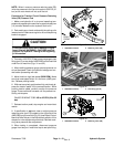
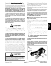
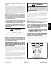
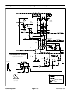
FRONT
1
2
Figure 38
CUTTING UNIT LOCATIONS
#4 #1 #5
#3#2
Hydraulic
System