


Reelmaster 7000Hydraulic System Page 4 -- 74
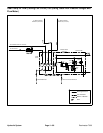
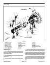
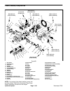
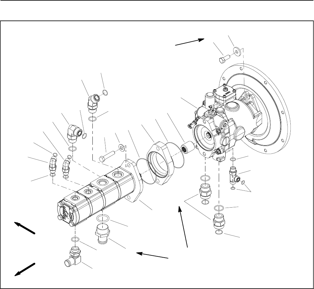
Gear Pump
1. Flat washer (2 used)
2. Cap screw (2 used)
3. 90
o
hydraulic fitting
4. Hydraulic tee fitting
5. O--ring
6. Gear pump assembly
7. Piston pump assembly
8. 90
o
hydraulic fitting
9. Coupler
10. 90
o
hydraulic fitting
11. O--ring
12. O--ring
13. 45
o
hydraulic fitting
14. Cap screw
15. Washer
16. O--ring
17. Spacer
18. O--ring
19. O--ring
20. Straight hose fitting
21. O--ring
22. Straight hydraulic fitting
23. O--ring
Figure 51
FRONT
RIGHT
1
2
3
4
23
16
6
12
8
9
10
13
5
21
11
18
17
20
19
14
15
22
7
5
11
11
12
8
16
18
77 to 93 ft--lb
(105 to 126 N--m)
103 to 118 ft--lb
(140 to 160 N--m)
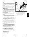
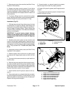
Removal (Fig. 51)
1. Park machine on a level surface, lower cutting units,
stop engine, engage parking brake and remove key
from the ignition switch.
2. Raiseseat and secure itwith prop rod to gainaccess
to gear pump.
3. Drain the hydraulic reservoir into a suitable contain-
er.
4. To prevent contamination ofhydraulic system during
removal, thoroughly clean exterior of pump and fittings.
5. Read the General Precautions for Removing and
Installing Hydraulic System Components at the begin-
ning of the Service and Repairs section of this chapter.
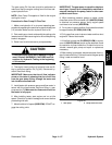
6. Disconnect hydraulic lines from gear pump and put
caps or plugs on open hydraulic lines and fittings. Label
disconnected hydraulic lines for proper assembly (Fig.
52).