


Reelmaster 7000 Hydraulic SystemPage 4 -- 127
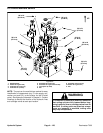
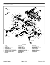
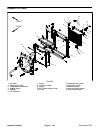
Removal (Fig. 95)
1. Park machine on a level surface, lower cutting units,
stop engine, engage parking brake and remove key
from the ignition switch.
2. Read the General Precautions for Removing and
Installing Hydraulic System Components at the begin-
ning of the Service and Repairs section of this chapter.
3. To prevent contamination ofhydraulic system during
lift cylinder removal, thoroughly clean exterior of lift cyl-
inder.
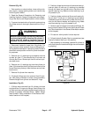
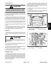
WARNING
Make sure that cutting units are fully loweredbe-
foreloosening hydrauliclines fromliftcylinder.If
cutting units are raised as hydraulic lines are
loosened, cutting units may drop unexpectedly.
4. Disconnect hydraulic hoses from lift cylinder. Put
caps or plugs onopen hydrauliclines andfittings to pre-
ventsystemcontamination.Labelthehydraulichosesto
show their correct position on the lift cylinder for assem-
bly purposes.
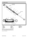
5. Remove one (1) retaining ring and washer from the
cylinder pin (item 17) that secures the lift cylinder rod
clevis to the lift arm. Remove pin from lift arm and cylin-
der shaft clevis.
6. Remove one (1) retaining ring from the cylinder pin
(item 15) that secures the lift cylinder barrel clevis to the
frame. Remove cylinder pin from the frame and cylinder
barrel clevis.
7. Remove lift cylinder from machine.
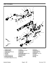
8. If hydraulic fittings are to be removed from lift cylin-
der, mark fitting orientation to allow correct assembly.
Remove fittings from cylinder and discard O--rings.
Installation (Fig. 95)
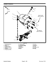
1. If fittings were removed from lift cylinder, lubricate
and place new O--rings onto fittings. Install fittings into
cylinderopenings usingmarksmadeduringtheremoval
process to properly orientate fittings. Tighten fittings
(see Hydraulic Fitting Installation in the General Infor-
mation section of this chapter).
2. Positioncylinder barrel clevisto frameand insertcyl-
inder pin (item 15) with one (1) retaining ring installed
through the frame and cylinder clevis. Secure pin with
second retaining ring. Make sure that retaining ring is
fully seated in pin.
3. Positioncylinder rod clevisto liftarm andinsert cylin-
der pin (item 17) with one (1) retaining ring and washer
installed through the lift arm and cylinder rod clevis. Se-
cure pin with second washer and retaining ring. Make
sure that retaining ring is fully seated in pin.
4. Remove caps and plugs from hoses and fittings. At-
tach hydraulic hoses to lift cylinder (see HydraulicHose
and Tube Installation in the General Information section
of this chapter).
5. Fill reservoir with hydraulic fluid as required.
6. Follow Hydraulic System Start--up procedures (see
Hydraulic System Start--up in this section).
7. After assembly is completed, operate lift cylinder to
verify that hydraulic hoses and fittingsare not contacted
by anything.
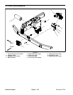
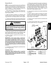
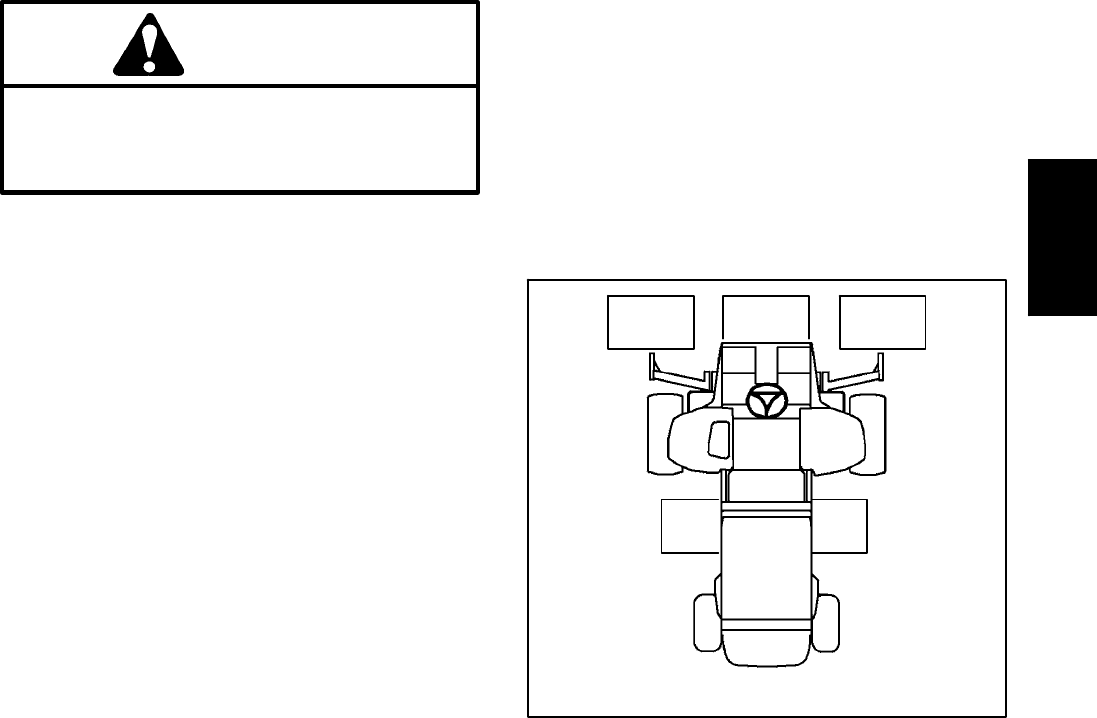
Figure 96
CUTTING UNIT LOCATIONS
#4 #1 #5
#3#2
Hydraulic
System