


Reelmaster 7000Hydraulic System Page 4 -- 120
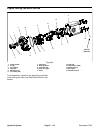
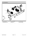
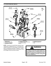
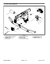
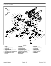
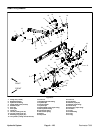
Lift Control Manifold Service
1. Manifold body
2. Relief valve (port RV2)
3. Solenoid valve (port S1)
4. Solenoid coil (5 used)
5. Solenoid valve (port S2)
6. Solenoid valve (ports S4 and S5)
7. Coil spacer (2 used)
8. Nut
9. Solenoid valve (port S3)
10. Relief valve (port RV1)
11. Nut
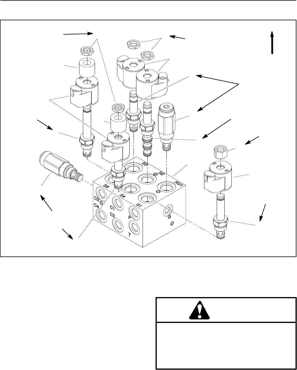
Figure 90
UP
60 in--lb
(6.8 N--m)
20 ft--lb
(27 N--m)
2
3
6
8
9
11
10
1
5
7
4
8
4
4
7
6
60 in--lb
(6.8 N--m)
20 ft--lb
(27 N--m)
20 ft--lb
(27 N--m)
60 in--lb
(6.8 N--m)
20 ft--lb
(27 N--m)
20 ft--lb
(27 N--m)
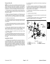
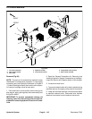
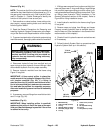
NOTE: The ports on the manifold are marked for easy
identification of components (e.g. P is the supply con-
nection port and RV1 is the location for the lift relief
valve). See Hydraulic Schematic inChapter 9 -- Foldout
Drawings to identify the function of the hydraulic lines
and cartridge valves at each port location.
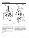
WARNING
If lift manifold is attached to machine, make sure
that cutting units are fully lowered before loos-
ening hydraulic lines orcartridge valvesfrom lift
manifold. If cutting units are raised as compo-
nents are loosened in manifold, cutting units
may drop unexpectedly.