


Reelmaster 7000
DPA Cutting Units
Page 8 -- 38
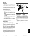
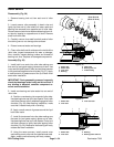
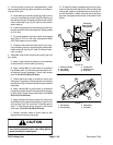
3. If drive bearing housing was disassembled, install
new components noting proper orientation as shown in
Figures 45 and 46.
A. Installbearing onshaft bypressing equallyon the
inner and outer bearing races. Install the bearing so
that the bearing seal is closest to theshoulder on the
shaft. Install snap ring (Fig. 45, item 6) onto shaft to
retain bearing.
B. Installnew grease seal into housing withthe lip of
the seal toward the driveshaft splines. Apply grease
to lip of seal.
C. Fill cavity between bearing location and grease
seal 50% to 75% full with high temperature Mobil
XHP--222 grease (or equivalent).
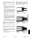
D. Carefully slide shaft and bearing fully into hous-
ing bore taking care to not damage the grease seal.
Install retaining ring (Fig. 45, item 5) to secure bear-
ing in housing.
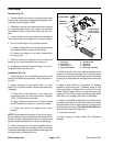
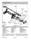
4. Assemble roller brush components using Figure 42
as a guide.
A. Apply a light coating of grease to inner diameter
of the grommet in drive bearing housing.
B. Apply Loctite #242 (or equivalent) to threads of
cap screws (item 13) that secure brush plate to driv-
en bearing housing assembly. Torque cap screws
from 15 to 19 ft-- lb (20 to 25 N--m).
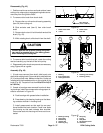
C. Check that brush plate is parallel to cutting unit
side plate.If necessary, change positionof mounting
bracket (item29) to allow brushplate to beparallel to
side plate.
D. Apply Loctite #242 (or equivalent) to threads of
flangehead screw(item 20)thatsecures drivepulley
to drive shaft. Torque flange head screw from 35 to
40 ft--lb (47 to 54 N--m).
E. Apply antiseize lubricant to splines of roller brush
shaft befores liding hardened washer(s) (item 9)and
driven pulley (item 10) onto shaft. Torque flange nut
(item 11) that secures driven pulley to roller brush
shaft from 15 to 19 ft--lb (20 to 25 N--m).
F. Position excluder seals on brush shaft so that
seals just touch bearing housings.
CAUTION
Contact with the reel or other cutting unit parts
can result in personal injury. Use heavy gloves
when handling the cutting reel.
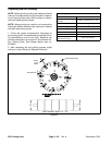
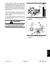
G. To install drivebelt, loop belt arounddriven pulley
and over the top of the idler pulley.While rotatingthe
cutting reel, carefully guide belt onto drive pulley. Af-
ter belt installation, make sure that belt and pulley
grooves are aligned and that belt is centered in idler
pulley.
1. Bearing housing
2. Drive shaft
3. Ball bearing
4. Grease seal
5. Retaining ring
6. Snap ring
Figure 46
Fill cavity
50 to 75% full
with grease
2
6
3
4
1
5
1. Drive pulley
2. Driven pulley
3. Idler pulley
4. Drive belt
Figure 47
2
3
1
4