


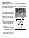

Reelmaster 7000Page 5 -- 32Electrical System
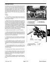
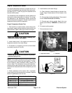
Reel Speed Potentiometer
The reel speed potentiometer controls the cutting reel
speed. The TEC controller uses the potentiometer set-
ting as aninput todetermine thenecessary voltageout-
put for the hydraulic mow control manifold proportional
valves(SP1 andSP2)forcorrect cuttingreelspeed. The
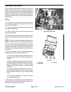
reel speed potentiometer is located under the operator
seat (Fig. 44).
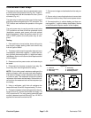
Testing
1. Park machine on a level surface, lower cutting units,
stop engine, engage parking brake and remove key
from the ignition switch.
2. Raise and support operator seat to gain access to
reel speed potentiometer.
3. Carefully unplug wire harness connector from reel
speed potentiometer.
4. Remove screw that secures potentiometer to ma-
chine and remove potentiometer from machine for test-
ing.
NOTE: Prior to taking small resistance readings with a
digital multimeter, short the meter test leads together.
The meter will display a small resistance value (usually
0.5 ohms or less). This resistance is due to the internal
resistance of the meter andtest leads. Subtract this val-
ue from fromthe measured value of the componentyou
are testing.
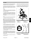
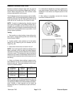
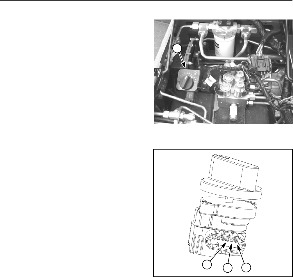
5. Using a multimeter, measure resistances between
potentiometer terminals as follows (Fig. 45):
A. Verify that resistance between terminals B and C
is approximately 5000 ohms. Record measured re-
sistance.
B. Measure resistance between terminals A and C
and then measure resistance between terminals A
andB. Recordthese resistances.The totalof thetwo
measured resistances should be approximately
5000 ohms.
C. Rotate the reel speed potentiometerto other set-
tings and repeat step 6. The total of the two resist-
ances should consistently be approximately 5000
ohms.
D. If measured resistances are incorrect, replace
reel speed potentiometer.
6. After testing is completed, secure potentiometer to
machine frame. Secure wire harness connector to po-
tentiometer. Lower and secure seat.
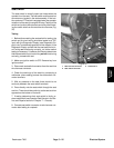
1. Reel speed potentiometer
Figure 44
1
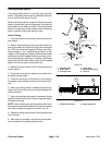
1. Terminal A
2. Terminal B
3. Terminal C
Figure 45
1
2
3