


Reelmaster 7000
DPA Cutting Units
Page 8 -- 37
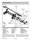
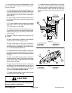
Disassembly (Fig. 42)
1. Positionmachine on a clean andlevel surface, lower
cutting units,stop engine, engage parkingbrake and re-
move key from the ignition switch.
2. To remove roller brush from brush shaft:
A. Remove the non--driven brush bearing assembly
(item 30) from cutting unit.
B. Slide excluder seal (item 6) from roller brush
shaft.
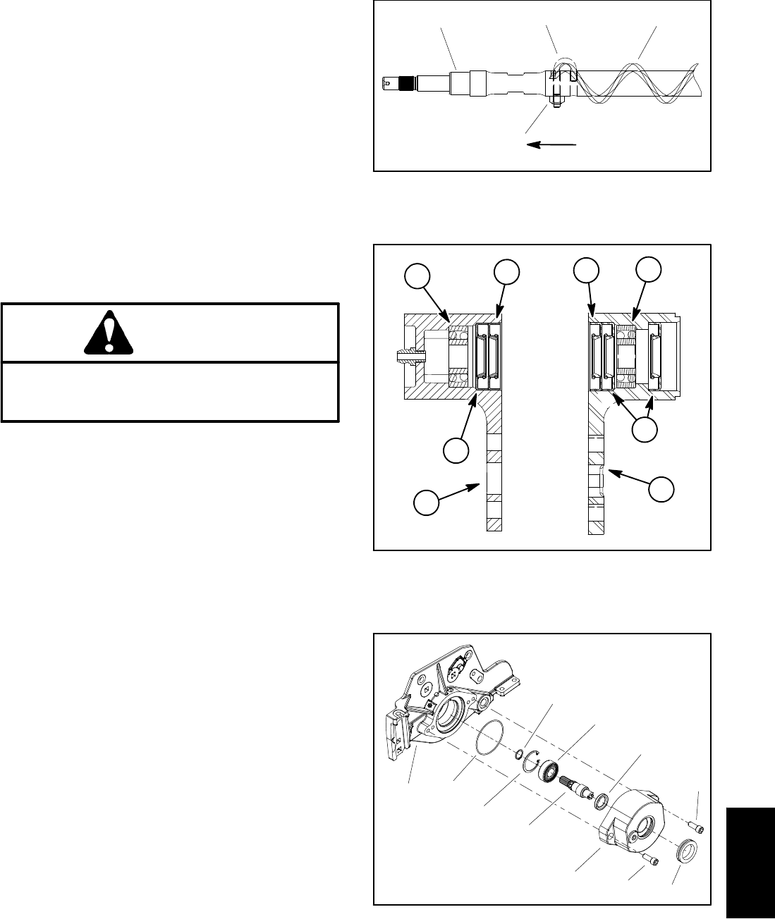
C. Removelock nutand J--boltfromboth endsof the
brush (Fig. 43).
D. While rotating brush, slide brush from the shaft.
CAUTION
Contact with the reel or other cutting unit parts
can result in personal injury. Use heavy gloves
when handling the cutting reel.
3. To remove roller brush drive belt, rotate the cutting
reel and carefully pry the belt off the drive pulley.
4. Disassemble roller brush components as necessary
using Figures 42 as a guide.
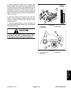
Assembly (Fig. 42)
1. If brush was removed from shaft, slide brush onto
shaftwhilerotatingbrush. Securebrushtoshaftwith two
(2) J--bolts and lock nuts.Make sure that the J--bolts are
installed with the threaded portion on the outside of the
brush(Fig. 43).Torquelocknuts from20to 25in--lb (2.3
to 2.8 N--m).
2. If seals or bearings were removed from brush bear-
ing housings, install new components notingproper ori-
entation as shown in Figure 44.
A. Pack bearings with grease before installation.
B. Press bearing into bearing housing s o that bear-
ing contacts shoulder in housing bore.
C. Install grease seals so that seal lips are posi-
tioned toward the brush location. Press inner seals
into housing so that seal contacts bore shoulder.
Press outer seals intohousing until inner seal is con-
tacted.
1. Roller brush shaft
2. J--bolt
3. Roller brush
4. Lock nut
Figure 43
1
2
3
4
20 to 25 in--lb
(2.3 to 2.8 N--m)
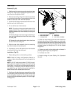
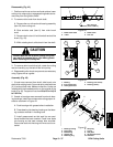
1. Bearing
2. Inner grease seal
3. Outer grease seal
4. Housing (non--driven)
5. Housing (driven)
Figure 44
2
2
1
1
4
5
3
3
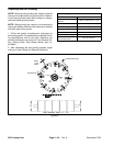
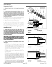
1. Bearing housing
2. Drive shaft
3. Ball bearing
4. Grease seal
5. Retaining ring
6. Snap ring
7. O--ring
8. Side plate
9. Socket head screw
10. Grommet
Figure 45
1
2
3
4
5
6
9
10
7
8
9
DPA Cutting
Units