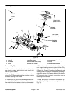
Reelmaster 7000Hydraulic System Page 4 -- 110
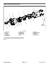
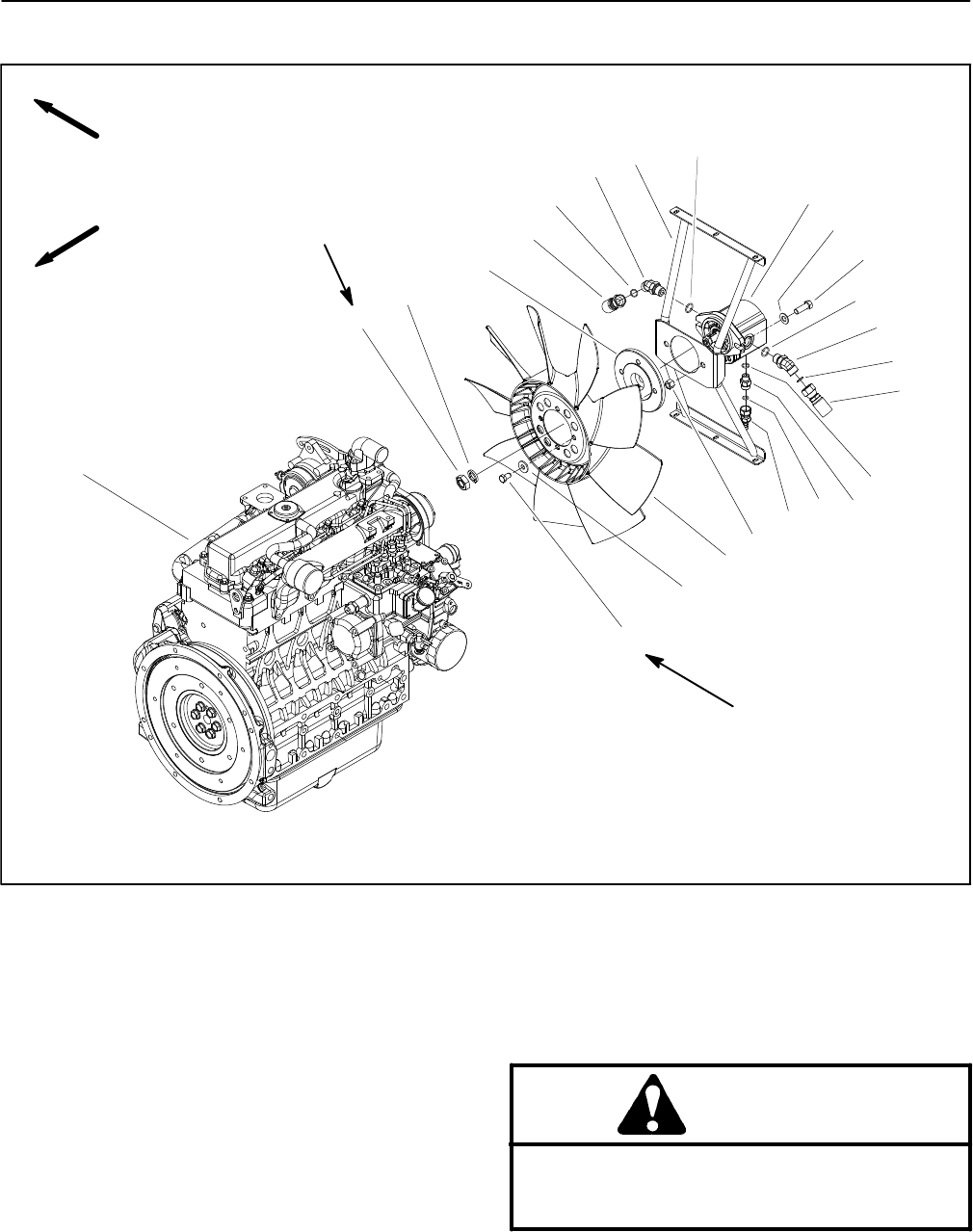
Engine Cooling Fan Motor
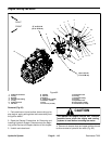
1. Hydraulic fan motor
2. O--ring
3. Bracket
4. 45
o
hydraulic fitting
5. O--ring
6. Hydraulic hose
7. Fan hub
8. Washer
9. Hex nut
10. Engine
11. Cap screw (4 used)
12. Washer (4 used)
13. Fan
14. Lock nut (2 used)
15. Hydraulic hose
16. O--ring
17. Hydraulic fitting
18. O--ring
19. Hydraulic hose
20. Cap screw (2 used)
21. Flat washer (2 used)
Figure 82
(37to44N--m)
27 to 33 ft--lb
(17to18N--m)
12 to 14 ft--lb
3
5
6
4
7
1
2
8
9
10
11
12
13
14
15
16
17
4
2
5
18
19
20
21
FRONT
RIGHT
Removal (Fig. 82)
1. Park machine on a level surface, lower cutting units,
stop engine, apply parking brake and remove key from
the ignition switch.
2. Read the General Precautions for Removing and
Installing Hydraulic System Components at the begin-
ning of the Service and Repairs section of this chapter.
3. Unlatch and raise hood.
CAUTION
The radiator and engine may be hot. To avoid
possible burns, allow the engine and cooling
systems to cool before removing fan motor.
4. Remove air cleaner hose and upper radiator shroud
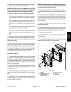
to allow access to hydraulic fan motor (Fig. 83).


