


Reelmaster 7000 Hydraulic SystemPage 4 -- 41
Procedure for Traction Circuit Relief Pressure Test
1. Make sure hydraulic oil is at normal operating tem-
peraturebyoperatingthemachineforapproximatelyten
(10) minutes. Make sure the hydraulic tank is full.
CAUTION
Movemachineto anopenarea,awayfrompeople
and obstructions.
2. Drive machine to an open area, lower cutting units,
turn the engine off and apply parking brake.
CAUTION
Prevent personal injury and/or damage to equip-
ment. Read all WARNINGS, CAUTIONS and Pre-
cautions for Hydraulic Testing at the beginning
of this section.
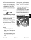
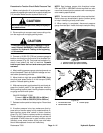
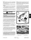
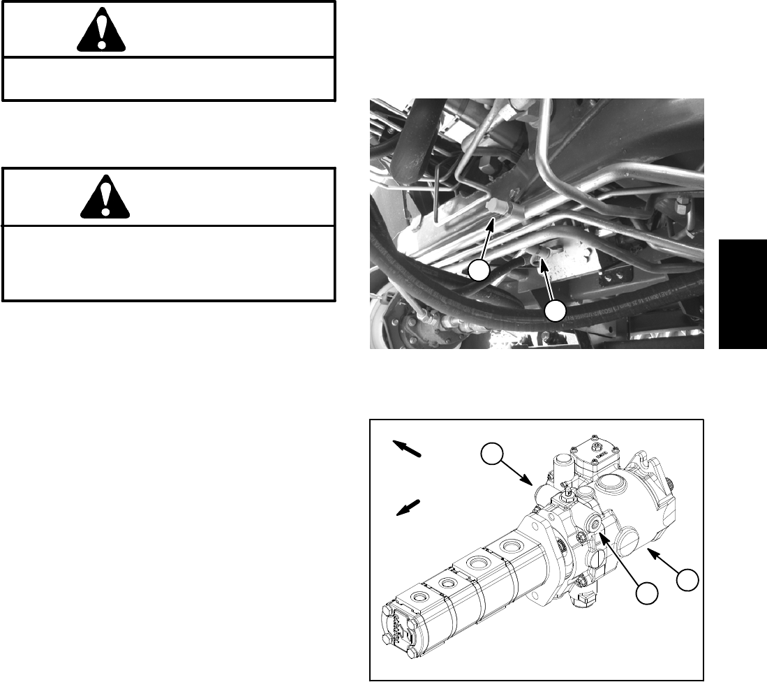
3. Connect a 10,000 PSI (700 bar) pressure gauge to
traction circuit test port for function to be checked (for-
ward or reverse) (Fig. 29). Test ports are located on hy-
draulic lines toward the front of machine. Forward
traction port faces the front and reverse port faces
rearward.
4. After installing pressure gauge, start engine and run
at low idle speed. Check for hydraulic leakage and cor-
rect before proceeding with test.
5. Move throttle to high idle speed (2850 RPM).Make
sure that mow speed limiter is in the transport (2WD)
position. Release parking brake.
6. Withseatoccupied, applybrakes fullyand slowlyde-
press the traction pedal in the appropriate direction.
While pushing traction pedal, identify pressure reading
on gauge as relief valve opens:
GAUGE READING TO BE:
Forward: 4800 to 5300 PSI (332 to 365 bar)
Reverse: 4800 to 5300 PSI (332 to 365 bar)
7. Release traction pedal and stop engine. Record test
results.
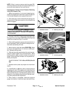
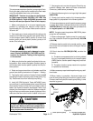
8. If traction pressure is too low, makes sure that by-
pass valve on traction pump is fully seated and then in-
spect traction pump relief valves in piston (traction)
pump ( Fig. 30). Clean or replace valves as necessary.
These cartridge type valves are factory set and are not
adjustable. If relief valves are in good condition, piston
(traction) pump, wheel motors and/or rear axle motor
should be suspected of wear and inefficiency.
NOTE: Seal leakage across pilot directional valves
PD1 and PD2 in 4WD/2WD control manifold can also
cause low forward traction pressure with reverse pres-
sure meeting specifications.
NOTE: Forward and reverse relief valves are identical.
Relief valves can be switched in piston (traction) pump
to help in identifying a faulty relief valve.
9. When testing is completed, disconnect pressure
gauge from test port. Install dust cap to test port fitting.
1. Forward traction port (faces forward)
2. Reverse traction port (faces rearward)
Figure 29
2
1
1. Forward relief valve
2. Reverse relief valve
3. Traction pump
Figure 30
2
3
FRONT
RIGHT
1
Hydraulic
System