


Reelmaster 7000 Hydraulic SystemPage 4 -- 25
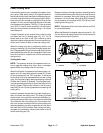
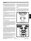
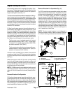
Engine Cooling Fan Circuit
A four section gear pump is coupled to the piston (trac-
tion) pump.The gear pumpsection P4(farthest fromthe
piston pump) supplies hydraulic flow for the hydraulic
engine cooling fan motor (Fig. 17).
Thefancontrolmanifold controlstheoperationofthehy-
draulic motor that drives the engine cooling fan in addi-
tionto includingthe flowdivider (FD)for thesteering and
lift circuits. The electronicallycontrolled proportionalre-
liefvalve (PRV)in themanifold controlsthe oilflow tothe
fan motor. The fan control manifold controls the speed
and direction of the fanmotor based on electricaloutput
from the TEC controller.
Oil flow from the gear pump to the cooling fan motor is
controlled by the proportional relief valve (PRV) in the
fan control manifold. This valve adjusts fan circuit flow
based on a PWM (Pulse Width Modulation) signal from
the TEC controller. The controller uses engine coolant
and hydraulic oil temperatures as inputs to determine
theproper PWM signalfor thePRVvalve. Thefan circuit
flow determines the speed of the cooling fan motor.
The fan motor runs at reduced speed until coolant
reaches approximately 165
o
F(74
o
C). The fanmotor
increases to full speed (approximately 2800 RPM)
as coolant reaches 180
o
F(82
o
C).
Thefanmotor automaticallyslows downandthen re-
verses direction if coolant reaches 203
o
F(95
o
C) or
hydraulic oil reaches 212
o
F (100
o
C).
If the fan motor is stalled for any reason, the manifold
proportionalrelief valve(PRV)has asecondary function
as a circuit relief to limit fan motor pressure to 3000 PSI
(207 bar).
When the engine is shut off, the over--running inertia
load of the fan blades keeps driving the fan motor and
turns itintoa pump.The check valve(CV) in thefan con-
trol manifold will open to keep the motor circuit full of oil
so the fan motor will not cavitate.
NOTE: IfPWM currentis not availableto the fancontrol
manifold proportional relief valve (PRV), the cooling fan
motor will run atfull speed in thenormal (forward) direc-
tion.
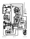
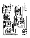
Forward Direction Fan Operation
Oilflow fromthe gearpump issentthrough thede--ener-
gized solenoid valve S1 to rotate the cooling fan motor.
Return flow from the motor re--enters the manifold (port
M2),through thede--energized solenoidvalve S1,out of
the manifold(port T)and thenis routed throughthe mow
control manifold, oil cooler and oil filter.
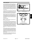
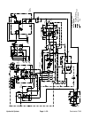
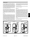
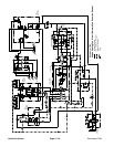
Reverse Direction Fan Operation (Fig. 18)
The TEC controller can reverse the cooling fan to clean
debris from the rear intake screen. If hydraulic oil and/or
engine coolant temperatures increase to an unsuitable
level or if the engine cooling fan switch is pressed to
manual reverse, a high PWM signal is sent to the PRV
valve to slow the cooling fan and direct pump oil flow
away from the fan motor. The controller then energizes
solenoid valve S1 in the fan control manifold to reverse
cooling fan motor oil flow so that the motor runs in the
reversedirection.A lowerPWMsignalis senttothePRV
valve allowingoil flowto returnto the fanmotor butin the
reverse direction causing the motor and cooling fan to
run in reverse for a short time.
NOTE: The fan reversal process is not designed to
clean the radiator of debris. Refer to Operator’s Manual
for radiator cleaning maintenance recommendations.
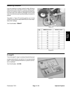
1. Gear pump
2. Fan control manifold
3. Fan circuit supply hose
4. Hydraulic fan motor
Figure 17
1
2
3
4
Figure 18
REVERSE
FROMGEAR
TOOILCOOLER
TORESERVOIR
TOLIFT/LOWER
CIRCUIT
TOSTEERING
CIRCUIT
PUMP(P3)
FROMGEAR
PUMP(P4)
DIRECTION
PRV
G1
G2
Hydraulic
System