


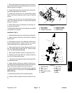
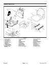
Reelmaster 7000 Page 7 -- 7 Chassis
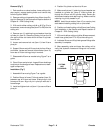
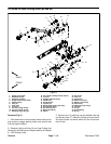
Disassembly (Fig. 5)
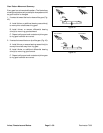
1. Park machine on a level surface, lower cutting units,
stop engine and engage parking brake. Remove key
from ignition switch.
2. Remove two (2) flange head screws (item 8) and
then cover plate (item 7) from outside of console arm.
Locate and retrieve two (2) flange spacers (item 37).
3. At front of console arm, remove screw (item 5) and
lock nut (item 6) thatsecure console arm covers to each
other.
4. Remove five (5) washer head screws (item 4) that
secure each cover to console arm panel.
5. Remove console arm covers from machine. As LH
cover(item 2)is removedfromconsole arm,unplug wire
harness connector from headlight switch.
6. Remove electrical components from console arm as
needed using Figure 5 as a guide.
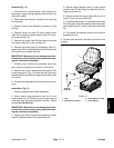
7. If necessary, remove console panel and supports
from machine using Figures 5 and 6 as guides.
Assembly (Fig. 5)
1. Install all removed electrical and console arm com-
ponents using Figure 5 and 6 as guides.
2. Position covers to console arm. As LH cover (item 2)
is placed, plug wire harness connector to headlight
switch.
3. Secureeachc over toconsole armwith five(5) wash-
er head screws (item 4). Install screw (item 5) and lock
nut (item 6) to secure covers at front of console arm.
4. Position cover plate and flange spacers to outside of
console arm. Secure with two (2) flange head screws.
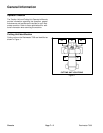
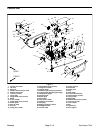
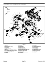
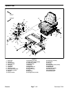
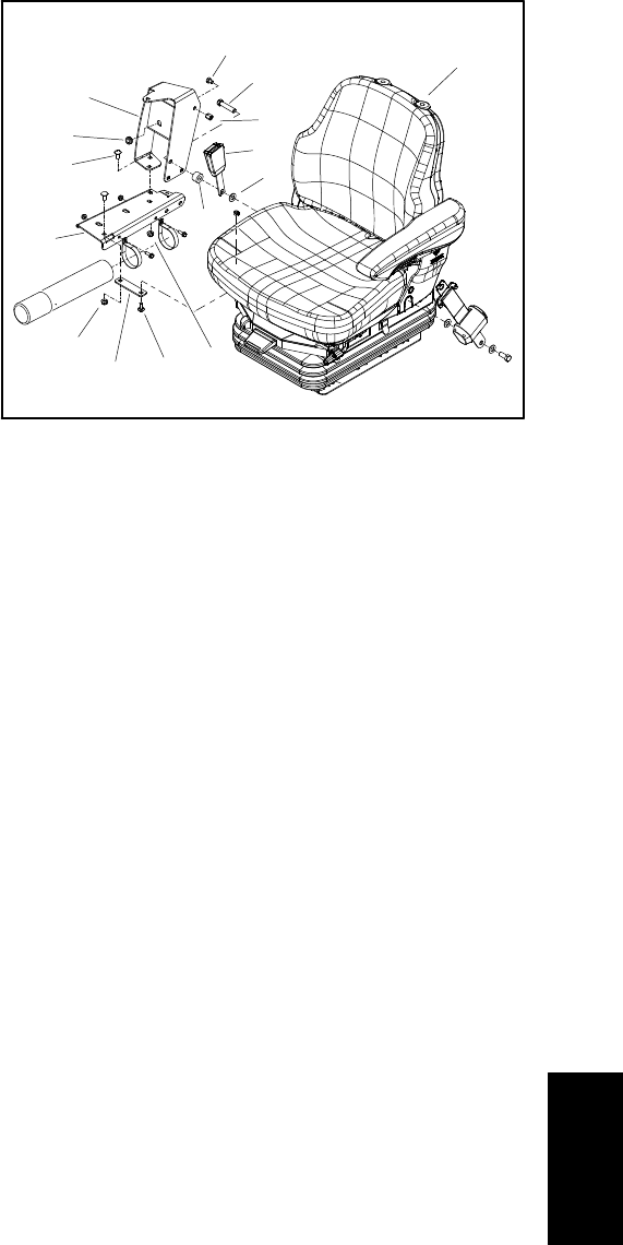
1. Flat washer
2. Seat belt buckle
3. Coupling nut
4. Spacer
5. Carriage screw (6 used)
6. Operator seat
7. Cap screw
8. Arm support
9. Grommet
10. Cap screw
11. Flange nut
12. Support channel
13. Support bracket
Figure 6
1
2
4
8
3
12
13
10
5
11
7
9
5
11
6
Chassis