


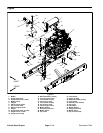


Reelmaster 7000 Page 3 -- 15 Kubota D iesel Engine
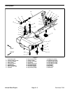
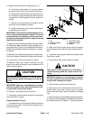
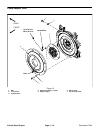
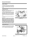
8. Install fan motor and fan assembly (Fig. 11).
A. Carefullypositionfan motor, fanandmotor brack-
et assembly to radiator.
B. Secure fan motor bracket to radiator with six (6)
cap screws and flange nuts.
C. Remove caps and plugs placed in hoses and fit-
tings during removal to prevent contamination.
D. Connect hydraulic hoses to cooling fan motor
(see Hydraulic Hose and Tube Installation in the
GeneralInformations ection ofChapter4 -- Hydraulic
System).
9. Position upper radiator shroud to the radiator. Secu-
re shroud to the radiator and lower radiator bracket w ith
removedfasteners (see RadiatorInstallation in thissec-
tion). Makesure that clearancebetween shroud and fan
is at least 0.180” (4.6 mm) at all points.
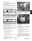
10.Connect throttle cable to engine (Fig. 9):
A. Secure throttle cable swivel to speed control le-
ver with lock nut.
B. Place throttle cable under cable clamp.
C. Adjust throttle cable position in cable clamp so
that engine governor lever contacts the high speed
stop bolt at the same time that the throttle lever con-
tacts the end of the slot in the control console.
D. Tighten cable clamp to secure throttle cable.
11.Remove caps from fuel hose and injector pump fuel
inlet that were placed during engine removal to prevent
contamination. Connect fuel supply hose to injection
pump (Fig. 9). Secure hose with hose clamp.
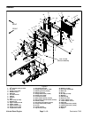
12.Connect wire harness connectors to the following
engine components:
A. The engine run solenoid (Fig. 9).
B. The temperature sender (Fig. 10).
C. The alternator (Fig. 10).
D. The glow plug connection.
E. Wire harness connector to engine ground har-
ness.
F. The electricstarter.TorquenutatstarterB+ termi-
nal from 70 to 86 in--lb (7.9 to 9.7 N--m).
G. Lowoilpressure switchlocated onalternator side
of engine (above electric starter).
13.Using notes taken during engine removal, secure
wires with cable ties in proper locations.
14.Install air cleaner assembly to the engine (see Air
Cleaner Installation in this section).
15.Installexhaust systemtomachine(seeExhaustSys-
tem Installation in this section).
16.Connect coolant hoses tothe radiator.Make sure ra-
diatordraincock isclosed.Fillradiator andreservoirwith
coolant.
17.Check position of wires, fuel lines, hydraulic hoses
and cables for proper clearance with rotating, high tem-
perature and moving components.
18.Connect positive battery cable first and then nega-
tive battery cable. Secure battery cover to machine.
19.Check and adjust engine oil level as needed.
20.Check and adjust hydraulic oil level as needed.
21.Bleed fuel system.
22.Operate hydraulic controls to properly fill hydraulic
system (see Charge Hydraulic System in the Service
and Repairs section of Chapter 4 -- Hydraulic Systems).
23.Install hood on the machine (see Hood Installation in
the Service and Repairs section of Chapter 7 -- Chas-
sis).
Kubota
Diesel Engine