


Reelmaster 7000Hydraulic System Page 4 -- 100
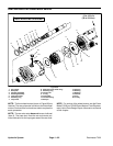
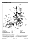
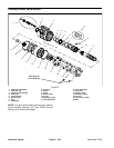
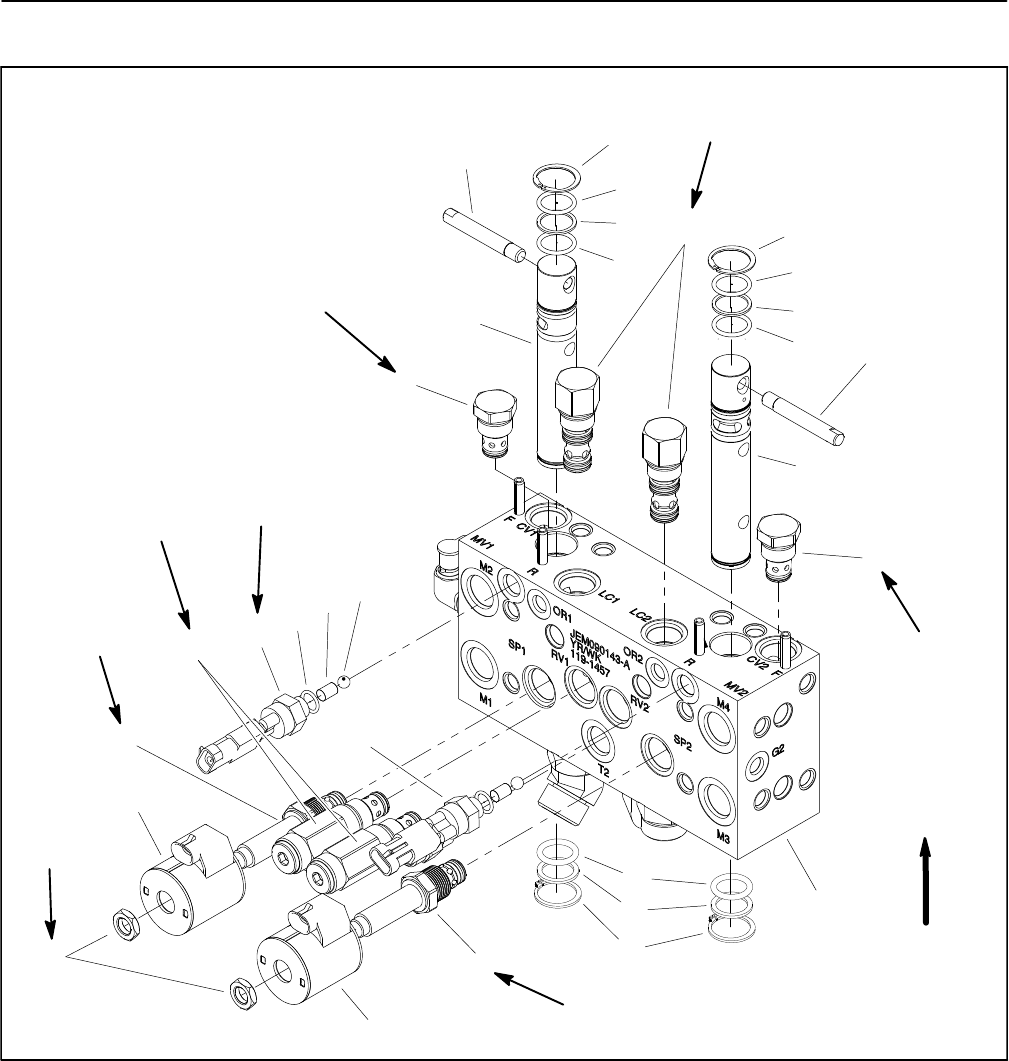
Mow Control Manifold Service
1. Manifold body
2. Proportional valve (SP1 & SP2)
3. Solenoid coil (2 used)
4. Relief valve (RV1 & RV2)
5. Pressure compensator (LC1 & LC2)
6. Check valve (CV1 & CV2)
7. Nut
8. Backlap switch (2 used)
9. O--ring
10. Dowel
11. Ball
12. Retaining ring (2 used per spool)
13. Backup ring
14. O--ring
15. O--ring
16. Backup ring
17. Backlap spool (2 used)
18. Spool handle
Figure 74
60 in--lb
(6.8 N--m)
UP
25 ft--lb
(34 N--m)
2
3
6
8
9
10
11
13
1
5
7
12
14
15
16
17
18
4
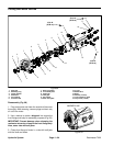
2
3
6
8
12
15
12
15
16
15
17
18
25 ft--lb
(34 N--m)
25 ft--lb
(34 N--m)
25 ft--lb
(34 N--m)
20 ft--lb
(27 N--m)
25 ft--lb
(34 N--m)
25 ft--lb
(34 N--m)
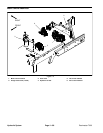
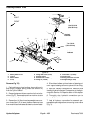
NOTE: The ports on the manifold are marked for easy
identification of components (e.g. P1 is a gear pump
connection port and PRV1 is the location for a propor-
tional relief valve). See Hydraulic Schematic in Chapter
9 -- Foldout Drawings to identify the function of the hy-
draulic lines and cartridge valves at each port location.
Cartridge Valve Service
1. For cartridge valve service procedures, see Control
Manifold Cartridge Valve Service in this section. Refer
to Figure 74 for cartridge valve installation torque.