


Reelmaster 7000Page 5 -- 26Electrical System
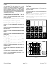
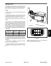
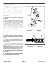
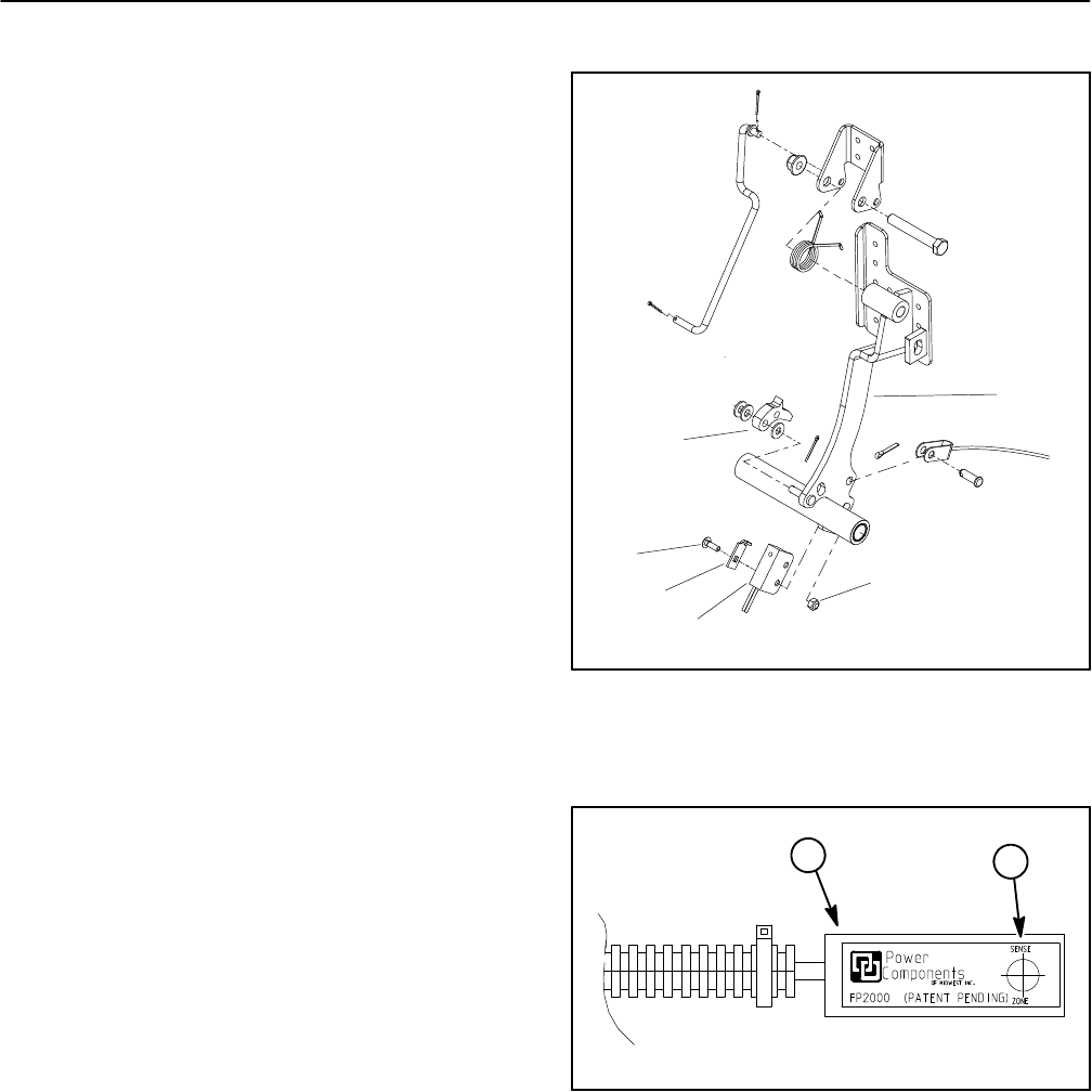
Parking Brake Switch
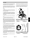
The parking brake switch is a normally open proximity
switch. The parking brake switch is attached to the bot-
tom of the RH brake pedal (Fig. 33).
Whentheparkingbrakeis notapplied,theparkingbrake
detent is positioned near the target end of the parking
brake switch so the switch is closed. The parking brake
detent is moved away from the switch when the parking
brake is applied causing the switch to open.
Switch Testing
1. Park machine on a level surface, lower cutting units,
stop engine.
2. Before disconnecting the parking brake switch for
testing, the switch and its circuit wiring should be tested
as a TEC input with the Diagnostic Display (see Diag-
nostic Display in the Troubleshooting section of this
chapter). Ifthe DiagnosticDisplay verifies thatthe brake
switchand circuitwiring arefunctioning correctly,no fur-
ther switch testing is necessary. If, however,the Display
determines that the brake switch and circuit wiring are
not functioning correctly, proceed with test.
3. Make sure ignition switch is OFF. Remove key from
ignition switch.
4. Disconnect wire harness electrical connector from
the parking brake switch.
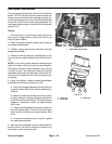
5. Check the continuity of the switch by connecting a
multimeter (ohms setting) across the connector termi-
nals.
6. When the parking brake is released (brake not ap-
plied), there should be continuity (closed) between the
switch terminals.
7. When the parking brake pedal is depressed (brake
applied), there should not be continuity (open) between
the switch terminals.
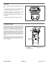
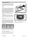
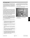
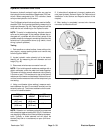
NOTE: When installing the parking brake switch to the
brake pedal, place switch plate tabinto switch mounting
hole that is closest to target end of switch (Fig. 34).
8. Replace parking brake switch if testing determines
that it is faulty.
9. After testing is complete, connectw ire harnesselec-
trical connector to the parking brake switch.
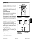
1. RH brake pedal
2. Brake detent
3. Carriage screw
4. Switch plate
5. Parking brake switch
6. Lock nut
Figure 33
2
3
4
5
1
6
1. Parking brake switch 2. Switch target area
Figure 34
2
1