


Reelmaster 7000 Hydraulic SystemPage 4 -- 133
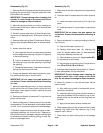
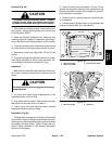
Removal (Fig. 99)
CAUTION
The radiator and oil cooler may be hot. To avoid
possible burns, allow the engine and cooling
systems to cool before working onthe oil cooler.
1. Park machine on a level surface, lower cutting units,
stop engine, engage parking brake and remove key
from the ignition switch.
2. Read the General Precautions for Removing and
Installing Hydraulic System Components at the begin-
ning of the Service and Repairs section of this chapter.
3. To prevent contamination ofhydraulic system during
oil cooler removal, thoroughly clean exterior of cooler.
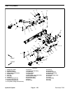
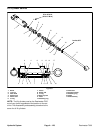
4. Remove oil cooler using Figures 99, 100 and 101 as
guides.
5. If hydraulic fittings areto be removed from oil cooler,
mark fitting orientation to allow correct assembly. Re-
move fittings from cooler and discard O--rings.
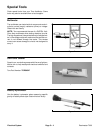
Inspection
1. Backflushoilcoolerwith cleaningsolvent.Aftercool-
er is clean, make sure all solvent is drained from the
cooler.
CAUTION
Use eye protection such as goggles when using
compressed air.
2. Dry inside of oil cooler using compressed air in the
opposite direction of the oil flow.
3. Plug both ends of oil cooler. Clean exterior of cooler.
Make sure fins are clear of dirt and debris.
4. The oil cooler should be free of corrosion, cracked
tubes and excessive pitting of tubes.
Installation (Fig. 99)
1. If fittings were removed from oil cooler, lubricate and
placenew O--rings ontofittings.Install fittingsintocooler
openingsusingmarksmadeduringtheremovalprocess
to properly orientate fittings. Tighten fittings (see Hy-
draulic Fitting Installation in the General Information
section of this chapter).
2. Install oil cooler using Figures 99, 100 and 101 as
guides. See Hydraulic Hose andTube Installation in the
General Information section of this chapter for hydraulic
hose installation information.
3. Check oil level in hydraulic reservoir and add correct
oil if necessary.
4. Follow Hydraulic System Start--up procedures (see
Hydraulic System Start--up in this section).
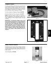
1. Wire form clamp
2. Hose to oil cooler
3. Hose from oil cooler
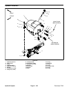
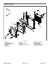
Figure 100
1
1
3
2
1. Wire form clamp 2. Oil cooler
Figure 101
1
2
1
Hydraulic
System