


Reelmaster 7000 Page 7 -- 5 Chassis
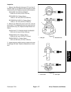
7. Slide rubber bellows up steering column to allow ac-
cess to fasteners that secure steering control valve and
steering column to machine.
8. Support steering control valve to prevent it from shif-
ting during steering column removal.
9. Loosen and remove four (4) socket head screws
(item 5) that secure steering control valve to steering
column.
10.Loosen and remove four (4) socket head screws
(item 9) and flange nuts (item 10) that secure steering
column to machine.
11.Raise steering column assembly from steering con-
trol valve and machine.
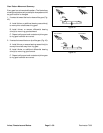
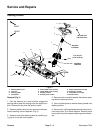
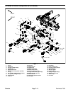
12.Disassemble steering column assembly as needed
using Figure 4 as a guide.
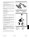
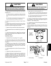
Installation (Fig. 2)
1. AssemblesteeringcolumnusingFigure4 asaguide.
2. Apply antiseize lubricant to input shaft of steering
control valve.
3. Slide steering column onto steering control valve.
Secure steering column in place with four (4) socket
head screws (item 9) and flange nuts (item 10).
4. Securesteeringcontrolvalvetosteeringc olumnwith
four (4) socket head screws (item 5). Torque screws
from 7 to 10 ft--lb (10 to 13 N--m).
5. Slide rubber bellows to bottom of steering column.
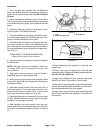
6. Position column brace (item 12) in place and secure
with four (4) flange head screws.
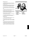
7. Thoroughlycleantaperedsurfaces ofsteeringwheel
and steering column.
8. Apply antiseize lubricant to splines of steering col-
umn takingc are to keep antiseizelubricant from column
taper. Slide steering wheel onto steering column.
9. Secure steering wheel to steering column with flat
washer and locknut. Torque hex nut from 20 to 26 ft--lb
(28to35N--m).
10.Install steering w heel cover to steering wheel.
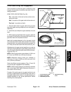
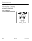
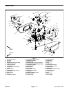
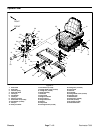
11.Install and secure platform shroud to machine (Fig.
3).
1. Roller support
2. Screw (2 used)
3. Carriage screw (2 used)
4. Headlight assembly
5. Flange nut (2 used)
6. Platform shroud
Figure 3
2
3
4
5
6
1
4
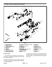
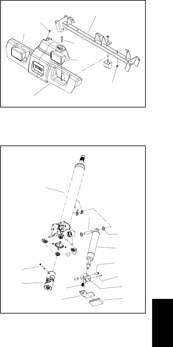
1. Steering column
2. Pin
3. Universal joint
4. Pin
5. Lock washer (2 used)
6. Cylinder
7. Bolt (2 used)
8. Pin
9. Pedal block
10. Pedal cover
11. Pedal
12. Spring
Figure 4
2
3
4
5
6
1
7
8
9
10
12
11
Chassis