


Reelmaster 7000 Hydraulic SystemPage 4 -- 101
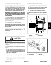
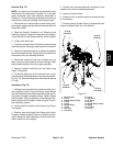
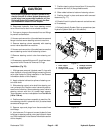
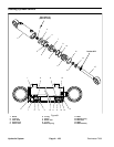
Mow/Backlap Spool Service (Fig. 74)
1. To remove backlap spool (item 17) from mow man-
ifold:
A. Remove backlap switch (item 8) from mow man-
ifold before removing mow/backlap spool. Remove
dowel pin and ball from manifold port after switch is
removed. Remove and discard O--ring from switch.
B. Remove lower retaining ring from backlap spool.
Raise backlap spool to allow access to retaining ring
on upper end ofspool. Remove upper retaining ring.
C. Push spool down until O--ring and back--up ring
are exposed on bottom of mow manifold. Remove
lower O--ring and back--up ring from spool.
D. Pull spool up and out of mow manifold. Remove
O--rings and back--up ring from spool.
E. Discard removed O--rings and back--up rings.
2. To installbacklapspool(item17)from mowmanifold:
A. Install O--rings and back--up ring to upper
grooves on backlap spool. Apply a light coating of
grease to O--rings.
B. Carefully push backlap spool down into mow
manifold port until lower O--ring and back--up ring
groove is exposedon bottom of manifold.Install low-
er O--ring and back--up ring to s pool. Apply a light
coating of grease to O--ring.
C. Carefullyraisebacklapspooluntilupperretaining
ring groove on spool is exposed on top of manifold.
Install upper retaining ring.
D. Pushbacklapspooldown andinstalllowerretain-
ing ring to spool.
E. If handle was removed from spool, position spool
so handle location of spool is between stop pins in
manifold.Apply Loctite603 RetainingCompound (or
equivalent) to threads on handle and install handle
into spool.
F. Place ball and dowel pin in backlap switch man-
ifold port. Install new O--ring onto backlap switch.
Thread backlap switch into port and torque 20 ft--lb
(27 N--m).
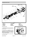
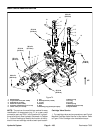
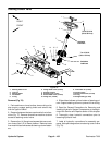
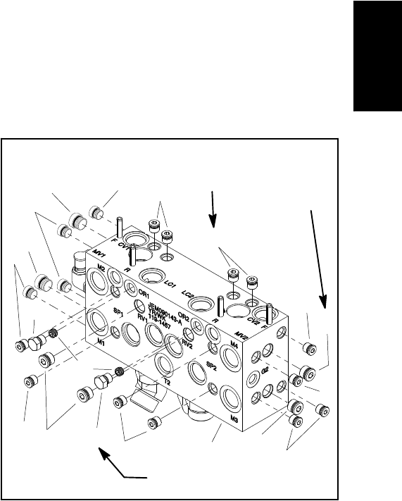
Manifold Plugs (Fig. 75)
NOTE: The mow control manifold uses several zero
leak plugs. These plugs have a tapered sealing surface
on the plug head that is designed to resist vibration in-
duced plug loosening. The zero leak plugs also havean
O--ring as a secondary seal. If zero leak plug removal is
necessary, lightly rap the plug head using a pin punch
andhammerbeforeusing anallenwrenchtoremovethe
plug:the impact willallow plugremoval with lesschance
of damage to the head of the plug.
IMPORTANT: An orifice is located beneath the plug
in mow control manifold ports OR1 and OR2. If an
orifice is removed from these manifold ports, make
sure to label its position for assembly purposes.
When installing the orifice in the manifold, make
sure thatthe orifice isproperly tightened inthe port.
1. RemoveplugsasneededusingFigure75asaguide.
Discard O--ring after plug removal.
2. Lubricate and place new O--ring onto removed
plugs.If plugwas removed fromport OR1or OR2,make
sure that orifice is correctly installed before threading
plug into manifold. Install plugs into manifold openings.
Torque#4 plugs to 20 ft--lb (27 N--m) and #6 plugs to 25
ft--lb (34 N--m).
1. Mow manifold
2. #4 zero leak plug
3. #6 zero leak plug
4. #4 zero leak plug
5. Orifice (.040)
Figure 75
1
2
3
4
5
2
2
2
2
2
2
2
2
3
3
3
3
4
2
20 ft--lb
(27 N--m)
25 ft--lb
(34 N--m)
20 ft--lb
(27 N--m)
Hydraulic
System