


Reelmaster 7000
DPA Cutting Units
Page 8 -- 21
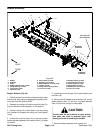
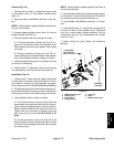
Removal (Fig. 24)
1. Remove lock nut (item 3), compression spring (item
2) and washer (item 11) from bedbar adjuster screw
(item 10).
2. Remove bedbar (see Bedbar Removal in this sec-
tion).
NOTE: Inside threads in bedbar adjuster shaft (item 4)
are left--hand threads.
3. Unscrew bedbar adjuster screw (item 10) from the
bedbar adjuster shaft (item 4).
4. Remove adjuster shaft from cutting unit frame:
A. On current production cutting units (Fig. 24), re-
move lock nut and flat washer from adjuster shaft.
Slide adjuster shaft and wave washer from cutting
unit frame.
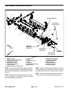
B. On early production cutting units (Fig. 25), re-
move retaining ring and wave washer from adjuster
shaft. Slide adjuster shaft from cutting unit frame.
5. Inspect flange bushings (item 5) in cutting unit frame
and remove if necessary.
6. If detent (item 7) is damaged, remove it from cutting
unit side plate by removing the cap screw (item 6).
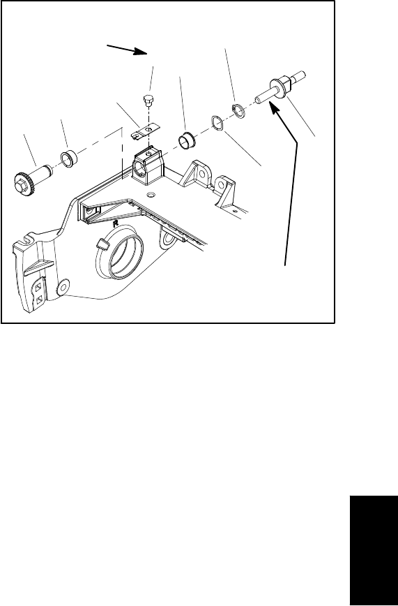
Installation (Fig. 24)
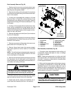
1. If detent (item 7) was removed, apply Loctite #242
(or equivalent) to threads of cap screw (item 6) and se-
cure detent to cutting unit side plate with cap screw.
Torque cap screw from 14 to 16 ft--lb (19 to 21 N--m).
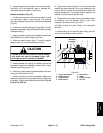
2. Ifflange bushings (item 5) werer emoved, apply anti-
seize lubricant to bore of cutting unit frame.Align key on
bushing to slot in frame and install bushings into frame.
3. Install adjuster shaft to cutting unit frame:
A. Oncurrentproduction cuttingunits(Fig. 24),slide
wave washer onto adjuster shaft and then slide ad-
juster shaftinto flangebushings in cutting unitframe.
Secure adjuster shaft with flat washer and lock nut.
Tighten lock nut to shoulder of adjuster shaft and
then torque lock nut from 15 to 20 ft--lb (21 to 27
N--m).
B. On early production cutting units (Fig. 25), slide
bedbar adjuster shaft into flange bushings in cutting
unit frame. Secure adjuster shaft with wave washer
and retaining ring.
NOTE: Inside threads in bedbar adjuster shaft (item 4)
are left--hand threads.
4. Applyantiseize lubricantto threadsofbedbar adjust-
erscrew (item10)thatfitinto adjustershaft.Threadbed-
bar adjuster screw into adjuster shaft (item 4).
5. Install bedbar (see Bedbar Installation in this sec-
tion).
6. Installwasher (item 11),compression spring (item 2)
and lock nut (item 3) onto adjuster screw. Tighten the
lock nut on each bedbar adjuster assembly until the
compression spring is fully compressed, then loosen
lock nut 1/2 turn.
7. Adjust cutting unit (see Cutting Unit Operator’s
Manual).
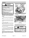
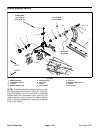
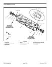
1. Bedbar adjuster screw
2. Retaining ring
3. Wave washer
4. Flange bushing
5. Cap screw
6. Detent
7. Bedbar adjuster shaft
Figure 25
4
6
7
5
4
3
2
1
Antiseize
Lubricant
14 to 16 ft--lb
(19to21N--m)
Loctite #242
DPA Cutting
Units